Edge Maxx Operating Principles
5-19
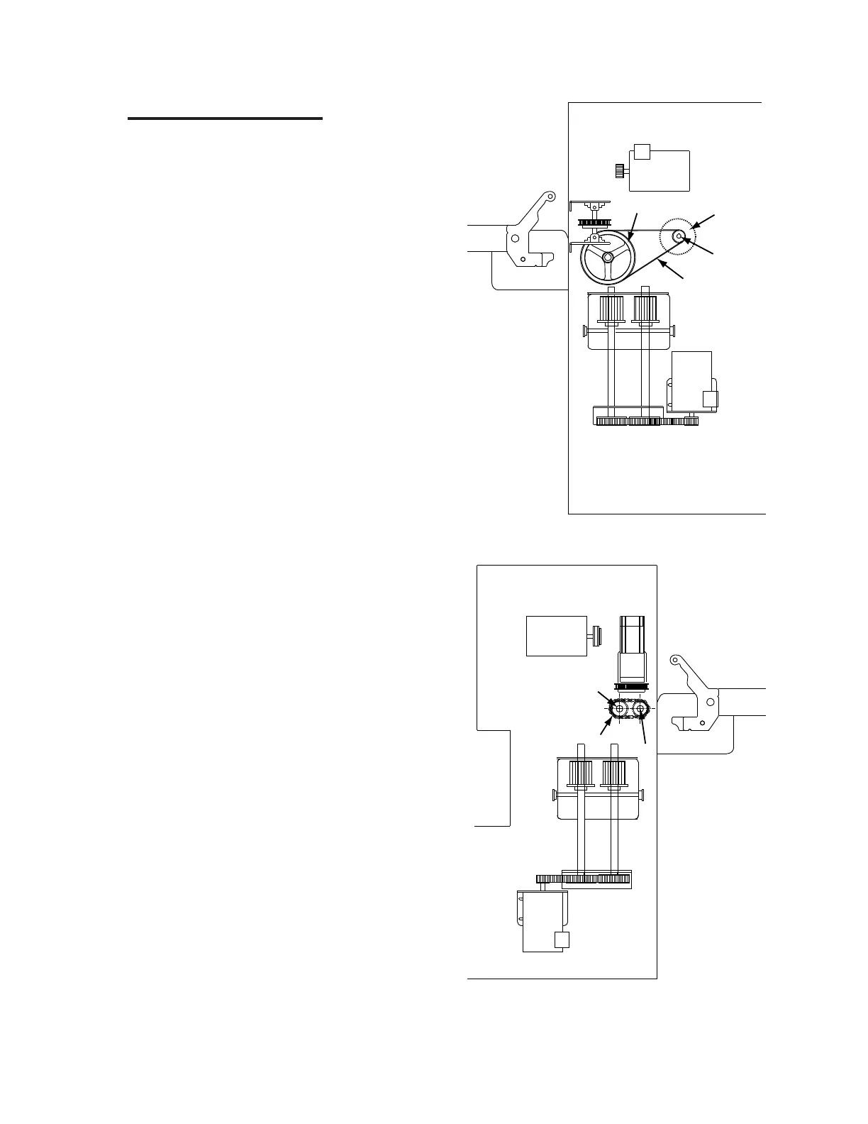
Discharge Drive System
Use the illustrations (Figures 5-21, 5-22) at
the right to identify the mechanical components
of the discharge drive system.
In the left endframe, the discharge motor
(Figure 5-21, A) powers the discharge drive
system. A shaft from this motor extends directly
into a drive pulley (B). This pulley drives a
belt (C) which in turn powers the large speed
reduction pulley (D).
This pulley is directly attached to the shaft
of the laydown assist roll and powers it. On the
other end of the assist roll in the right endframe
is a gear (Figure 5-22, E).
This gear drives a chain (F) which in turn
powers another, slightly smaller gear (G). This
gear is directly attached to the discharge ribbon
drive roll and powers it, moving flatwork toward
the next machine.
Because the discharge ribbon drive roll gear
is slightly smaller than the laydown assist roll
gear, the drive roll turns slightly faster, causing
the flatwork to stretch slightly as it travels down
the discharge ribbons.
Figure 5-21: Discharge components—left endframe.
Figure 5-22: Discharge components—right
endframe.
 Loading...