Edge Maxx Operating Principles
5-17
A second set of pulleys (R, S) on shaft Q power
the second set of twist belts (T, U). These belts
transmit power to the pneumatically controlled
brake-clutch mechanisms (V, W) which control
two drive rolls (3, 4) which press against the idler
rolls 1 and 2.
After the flatwork is in position, the upper and
lower inlet ribbons pressing together work along
with rolls 1, 2, 3 and 4 to help pull flatwork into
the machine.
Transfer Drive System
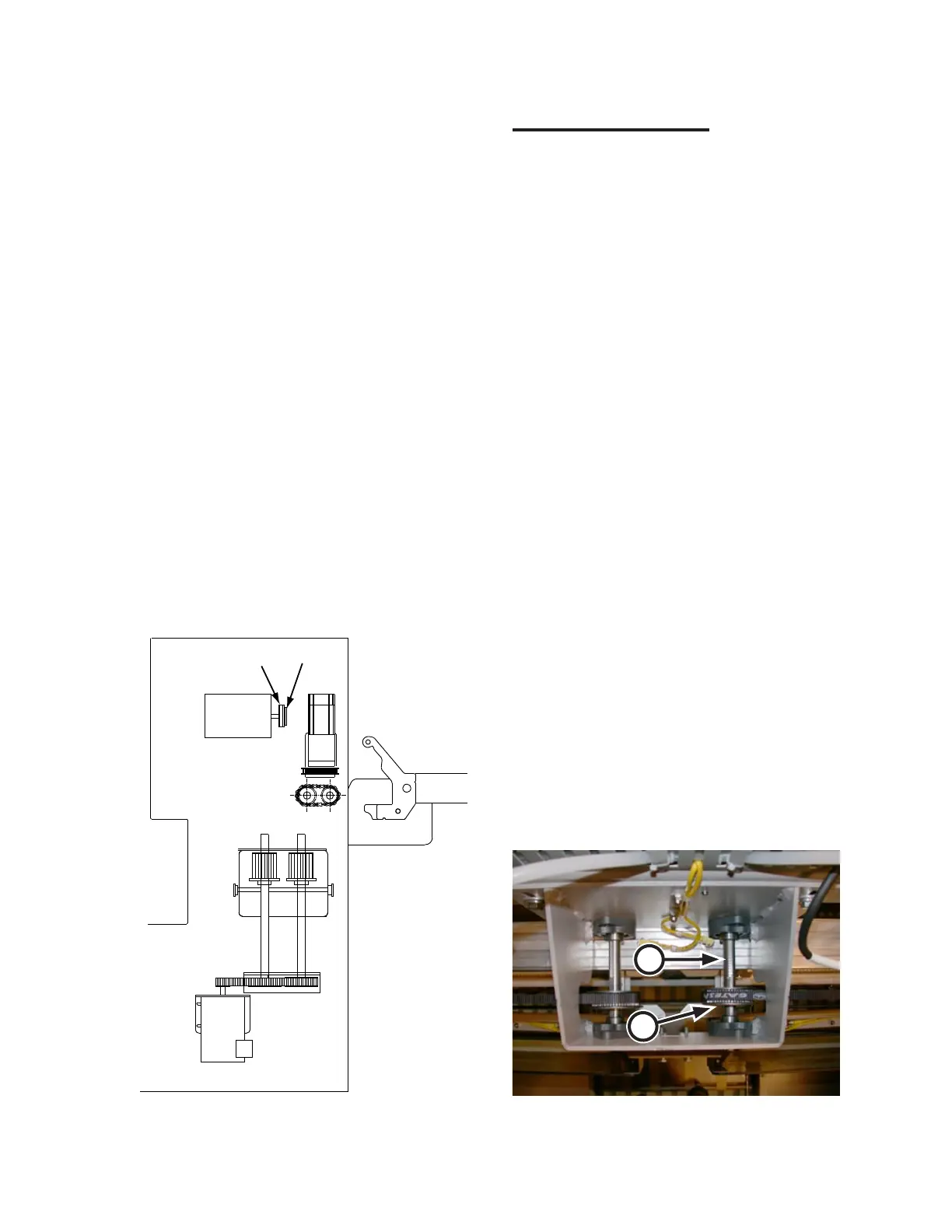
Use the illustration (Figure 5-17) and picture
(Figure 5-18) below to identify the mechanical
components of the transfer drive system.
This discussion will cover the right side transfer
components. An identical set of equipment
handles the left side transfer action.
In the right endframe, the right transfer motor
(Figure 5-17, A) powers the right transfer system.
A shaft from this motor extends directly into a
drive pulley (B).
This pulley drives a belt (Figure 5-17, C)
which spans to the middle of the machine to
another pulley (Figure 5-18, D) which sits on a
jackshaft (E).
When the belt moves, the right transfer
assembly, attached to the lower portion of the
belt, moves either toward the center transfer/
spread transition section or back toward its home
position at the right station inlet.
The forward and backward movement of the
transfer assembly and the action of the transfer
jaws is pneumatically controlled.
Figure 5-17: Transfer components—right endframe.
Figure 5-18: Transfer components-machine center.
D
E
 Loading...