Edge Maxx Operating Principles
5-21
5.4 Sequence of Operation
The unit has 6 phases of operation. In addition,
it will react to various error conditions.
Stand-by Phase
Start-up Phase
Input Phase
Transfer Phase
Spread Phase
Discharge Phase
Reject Phase
Error Conditions
•
•
•
•
•
•
•
•
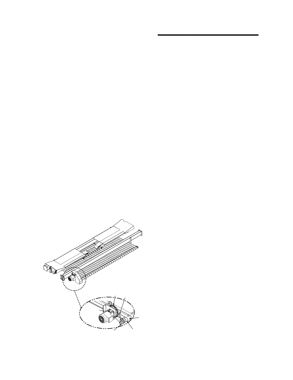
Figure 5-25: Reject components—machine rear.
Reject Conveyor Drive Subsystem
Use the illustration (Figure 5-24) below to
identify the mechanical components of the reject
conveyor drive system.
At the rear of the machine, a motor (Figure
5-25, A) powers the reject drive system. A shaft
from the drive motor extends directly into a gear
reducer (B). The output shaft is connected to a
drive pulley (C).
This pulley in turn powers a belt (D) which
in turn powers another pulley (E). This pulley is
attached to the end of the reject conveyor drive
roll (F), which moves the conveyor ribbons (G),
conveying rejected flatwork to the front of the
machine.