Edge MAXX Repair
7-15
The second worker will remove the bolts
which secure the two non-eccentric bear-
ings (Figure 7-17, B). Keep track of the
bolts and the flat washer which sits under
the bearing.
Carefully lower the rodless air cylinder/
transfer clamp assembly until it rests on
the machine.
If replacing the eccentric bearings, remove
them from their mounting block.
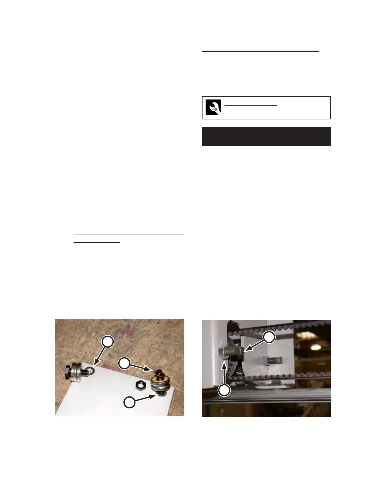
Install the new eccentric bearings, being
careful to place the two flat washers in the
correct position (Figure 7-18, A, B).
Carefully lift the rodless air cylinder/trans
-
fer clamp assembly back into position and
install the non-eccentric bearings. Make
sure the flat washer is in the correct potion
(Figure 7-18, C).
Adjust the bearing tension following the
Transfer Clamp Grooved Bearing Ten
-
sion Adjustment procedure earlier in this
section.
Replace the adjustment wrenches in their
cloth bag in the right endframe.
4.
5.
6.
7.
8.
9.
10.
A
Figure 7-18: Make Sure the flat washers are
correctly positioned when installing
new grooved bearings.
B
C
Transfer Belt Tension Adjustment
Adjust tension on either of the station spreader
belts when it begins to sag noticeably or to skip on
the timed pulley. Both conditions cause excessive
wear on the belt and shorten its life.
Required Tools
9/16”, 3/8” wrenches
Perform only when the unit is OFF
with power disconnected.
Turn power OFF at the main disconnect
switch.
Locate appropriate transfer belt tension
adjustment bolts in the center section of
the machine (Figure 7-19, A).
Loosen the locknuts (Figure 7-19, B)
and turn each bolt the same number of
turns clockwise until the belt is properly
tensioned.
Tighten the locknuts to secure the adjust-
ment.
Start the unit and feed several pieces to
verify the adjustment.
Repeat Steps 1 to 5 until the adjustment
is satisfactory.
1.
2.
3.
4.
5.
6.
Figure 7-19: Transfer belt tension adjustment
screws are located in the middle of the
machine.
A
B


 To Next Page