Edge MAXX Installation
2-13
Ironer Encoder Wheel (option)
Installation
This option allows the spreader/feeder to get its
automatic speed control signal from an encoder
wheel when the unit is paired with a non-Chicago
ironer.
Required Tools
screwdriver, 5/8” wrench, plastic wire
ties
Attach the encoder bracket at the left rear
of the discharge conveyor (Figure 2-21, A)
using the holes and hardware provided.
Connect the encoder signal wire to the
encoder wheel (Figure 2-21, B).
Route the signal wire along the inside of
the discharge conveyor arm (Figure 2-22)
and into the left endframe of the unit.
Open the left endframe door.
Route the wire as indicated in Figure 2-23.
Use the provided cable anchors.
Connect the cable wires to the terminal
block (Figure 2-20) as follows:
White (signal) to terminal 3.
Black (-24VDC) to terminal 9.
Red (+24VDC) to terminal 11.
Use plastic wire ties to secure the wire as
necessary.
Close and secure the left endframe door.
Make sure the encoder wheel rests on the
ironer’s input ribbons and makes good
contact for reliable rotation.
1.
2.
3.
4.
5.
6.
•
•
•
7.
8.
9.
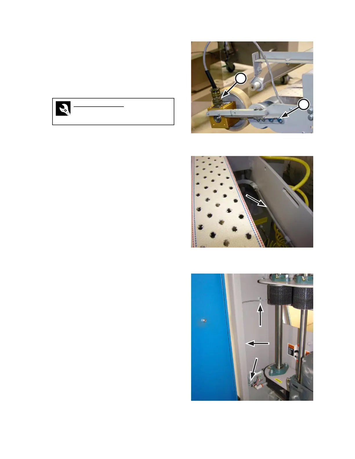
Figure 2-21: Attach the optional encoder wheel to
the left side of the discharge conveyor.
A
B
Figure 2-22: Route the cable along the inside of the
discharge conveyor left arm and into
the left endframe.
Figure 2-23: Use the provided anchors to route the
encoder cable.
 Loading...