Preventive Maintenance Edge MAXX
4-8
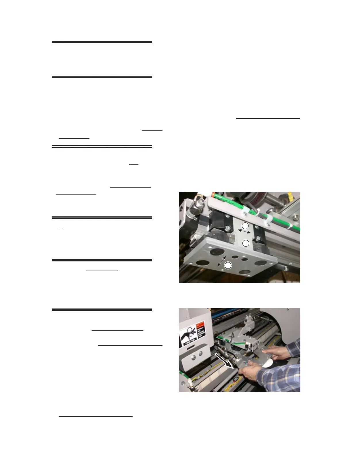
NOTE: The carriage assembly
is shown with the index clamp
center plate removed for clarity.
Grasp the base of the drive T (Figure 4-8,
A) and check to see whether there is any
looseness.
If any looseness is felt, the drive T must
be tightened before moving on to the next
step. Refer to the Repair section, Tighten
the Drive T
procedure.
NOTE: If it was necessary
to tighten the drive T, it will be
necessary to adjust the drive
blocks. Skip the next two steps
and perform the Tighten the
Drive Blocks procedure in the
Repair section and then go to
Step 9.
If the drive T is secure, check the drive
blocks and make sure they are tight against
the drive T by moving the carriage assem-
bly back and forth (Figure 4-8, B).
CAUTION
Failure to keep the drive
blocks tight against the
drive T can lead to
cascading problems.
Any “play” between the drive blocks and
the drive T must be eliminated before
going on to the next step. Refer to the
Repair section, Tighten the Drive Blocks
procedure.
Grasp the carriage assembly (Figure 4-8,
C) check to see whether there is any loose
-
ness by trying to wiggle it laterally.
If any looseness is felt, the carriage block
must be tightened before moving on to
the next step. Refer to the
Repair section,
Tighten the Carriage Block procedure.
5.
6.
7.
8.
9.
10.
Push the carriage assembly back to the
end of its stroke.
Slowly and steadily pull the carriage as-
sembly forward (Figure 4-9). Just before
it reaches the end, you should feel a slight
resistance from the air cushion.
If no resistance is felt, the air cushion
pressure must be increased. Refer to the
Repair section, Increase the Air Cushion
procedure.
Once the adjustment is made, repeat Steps
11 to 13.
Repeat Steps 11 to 14 for the back of the
air cylinder’s stroke.
Repeat Steps 4 to 15 for the other station’s
rodless air cylinder.
11.
12.
13.
14.
15.
16.
Figure 4-8: Three tests checks ensure that various
components of the carriage assembly
are secure.
A
C
B
Figure 4-9: Use steady pressure to pull down on
the carriage assembly to properly
check for the air cushion.
 Loading...