Multi-Channel Sync Hipot Tester 19020/19020-4/19021/19021-4/19022/19022-4
User’s Manual
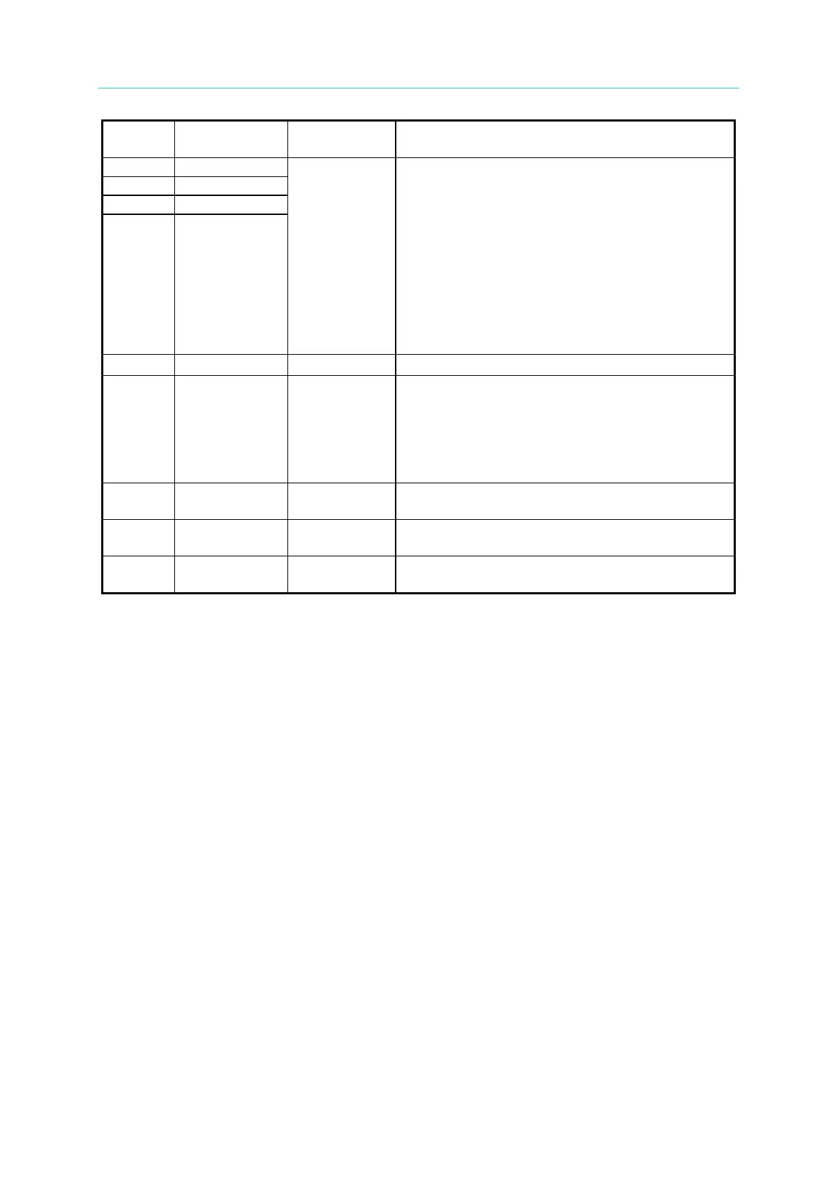
15 +VEXT
-
It is the external DC voltage input. The input
voltage range is between +3V~+26V.
Input
nRecall1~nRecall3 signals indicate the memory
position to be read.
It uses 3 bits to present 7 test steps.
The input format is binary code (001~011)
(nRecall1 is the low bit, while nRecall3 is the
high bit.)
001 means to recall memory 1
111 means to recall memory 7
nRecall4 signal is the switch for reading
memory. When nRecall4 inputs a LOW level
signal, the memory data can be retrieved.
19 nRecall4
-
It is the internal DC voltage output.
21 nEOS Output
The output signal of nEOS indicates if the test
is ended.
When the signal is HIGH, it means the test is
undergoing.
When the signal is LOW, it means the test is
22 GNDF
-
It is the external DC voltage input and the low
voltage terminal for input/output signal.
23 GD3
-
It is the low voltage terminal for internal voltage
output.
24 nPA_MODE Output
This signal will change once when running PA
Mode.