Operation
until the STOP key on Tester is pressed. The test result will show FAIL state.
FAIL State:
The resistance measured exceeds the range or the set high/low
limit.
To stop test output in any condition, just press STOP.
4.8.4 Procedure for OSC Test
1. Connect the UUT properly following the connection method.
2. In the power on screen shown below:
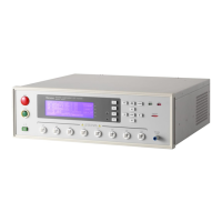
OSC
Illustration:
OSC means it is in Open Short Check mode. “Position 1” is the setting voltage and
“Position 2” is the standard capacitance (Cs) while “Position 3” shows the test result.
3. Press STOP to prepare for test. The status line shows “STANDBY”.
4. Press START to activate the test
When this key is pressed it starts to output voltage and the DANGER LED is on. The
status line shows a counter to count down. “Position 1” will show the output voltage value,
“Position 2” will show the current readings and “Position 3” will show the test result.
5. GOOD Judgment
When all tests are done and the results show PASS, the Tester will see the UUT as a
GOOD product and cutoff the output. The HANDLER interface outputs PASS signal and
the beeper acts at the same time.
6. NO GOOD Judgment
If the test value is abnormal, the Tester judges it as FAIL and cutoff the output
immediately. The HANDLER outputs FAIL signal and the beeper acts at the same time
until the STOP key on Tester is pressed. The test result will show FAIL state.