GE+ ACDC Installation and operation manual v11
11 / 121
2.4. Configuration and control of the power supply
The power supply can be interfaced by three means:
- Local touchscreen: a 4.3” colour local touchscreen panel can be used to configure,
monitor and operate the grid emulator. See section Local Touchscreen Control Panel for
further information.
- Analog/Digital inputs/outputs: the converter owns 6 isolated analog inputs (+/-10V) and
two optocoupled digital inputs. The converter owns 6 analogue outputs and 3 digital
outputs (8mA max).
- Remote interface: an Ethernet communication interface with protocol MODBUS/TCP
can be used to configure, monitor and operate the grid emulator. By using HMI software
application provided by CINERGIA, downloading of excel files is also possible.
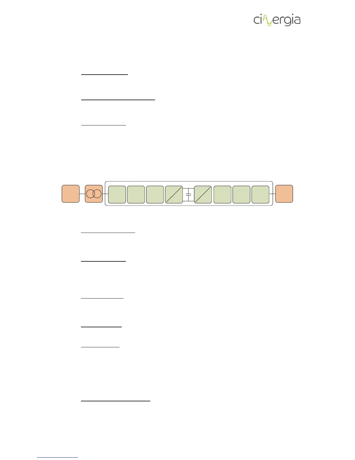
2.5. Functional diagram
The diagram below is the conceptual functions blocks diagram of the power supply:
AC
ACTIVE RECTIFIER
GRID
DC AC
DC
LOAD
DC/AC
Input LCL
filter
Input EMI
filter
Protections Protections
Output EMI
filter
Output LC
filter
OPTIONAL
The main components of the diagram are the following (from grid side to load side):
- Isolation transformer: a 50/60Hz isolation transformer can be provided optionally to
isolate the output phases. In this case, an isolation monitor can be integrated in the
power supply to detect isolation faults too.
- Input protections: these protections include a thermal-magnetic circuit breaker and
fuses. The connection of the power supply input with the grid is done by screw
terminals. Please follow safety instructions in Installation section to connect the grid
emulator.
- Input EMI filter: an electromagnetic filter is integrated to fulfil electromagnetic
compatibility regulations. The structure of the filter in question is the same as the one
of the output EMI filter.
- Input LCL filter: the purpose of this filter is to reduce the current distortion at
frequencies equal to or higher than switching frequency and thus reduce THD.
- Active Rectifier: a three-branch IGBT active front end is integrated in the equipment to
consume/inject a sinusoidal current from/to the grid.
The DC link voltage is set to 860V providing a regulation margin for fast transients at the
output of the grid emulator.
The active rectifier has bidirectional power flow capability and the injected reactive
power (grid side) can be defined by the customer.
- DC/AC output power supply: it is a three-branch IGBT converter. Its topology is the three
phase inverter and allows the conversion from the DC bus to each of the output AC
phases.