GE+ ACDC Installation and operation manual v11
23 / 121
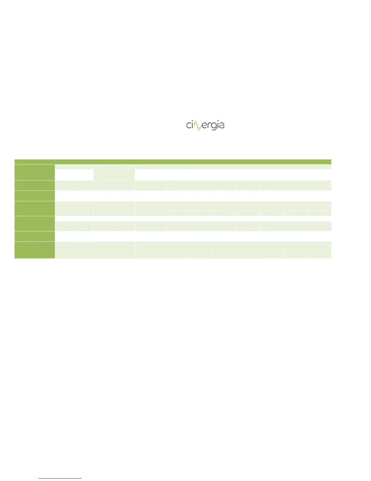
3.5. Configuration values of protection and wires
Nomenclature Description Characteristics CNG7.5 CNG10 CNG15 CNG20 CNG 30 CNG40 CNG50 CNG 60
A Mains RCCB Rated residual current
300mA to 500mA type
B
(for each
equipment)
16A 16A 25A 32A 50A 63A 80A 100A
B1 and B2 Input/Output MCB
type C
4P – 400Vac – 230Vac
coil type C
16A 16A 25A 32A 50A 63A 80A 100A
C – OPTION A MCB type C 4P – 400Vac – 230Vac
coil type D
16A 16A 25A 32A 50A 63A 80A 100A
C – OPTION B MCB type D 4P – 400Vac – 230Vac
coil type D
Depends on Power Transformer - two times of rated current of the transformer (take the same power as rated power
of the equipment)
32A 32A 50A 63A 100A 125A 160A 200A
W1 (*) General rectifier line cable section
Configuration 1+0 /
1+1
RZ1-K 4 mm
2
4 mm
2
6 mm
2
6 mm
2
10 mm
2
16 mm
2
25 mm
2
35 mm
2
W2 (*) Individual rectifier
line cable section
RZ1-K 4 mm
2
4 mm
2
6 mm
2
6 mm
2
10 mm
2
16 mm
2
25 mm
2
35 mm
2
W3 (*) Individual rectifier
line cable section
RZ1-K Depends on Power Transformer - two times of rated current of the transformer (take the same power as rated power
of the equipment)
6 mm
2
6 mm
2
10 mm
2
16 mm
2
25 mm
2
35 mm
2
50 mm
2
70 mm
2