GE+ ACDC Installation and operation manual v11
38 / 121
DIGITAL INPUT (Operation of the equipment):
- PIN 7: INPUT RESET. Makes a RESET to the equipment.
- PIN 8: INPUT RUN/READY. Changes from RUN to READY and vice versa.
- PIN 10: INPUT ENABLE/DISABLE. Changes from ENABLE to DISABLE and vice versa.
- PIN 13: INPUT TRIGGER (GE). Only available with GE. Allows the start of a configured
fault.
OUTPUT:
- PIN 5: READY LED. The output will turn on when the equipment is in READY state.
- PIN 3: RUN LED. The output will turn on when the equipment is in RUN state.
- PIN 4: ALARM LED. The output will turn on when the equipment is in ALARM state.
4.4.9. Analogue inputs and outputs (AIO)
III. Voltage amplifier
The GE converter can work as a voltage amplifier from the analogue inputs. It means that the
waveform in the analogue input will appear in the output of the converter knowing that the
working range of the analogue input goes from -10Vdc to 10Vdc and the output of the GE
goes from 0V to 277V. The equivalence of the voltages is shown in the table 2 of the following
pages of this manual.
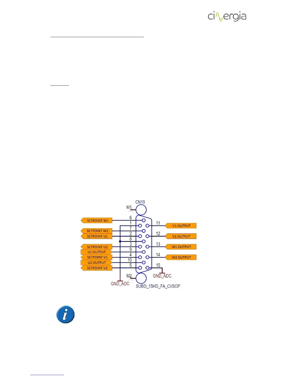
IV. Analogue inputs/outputs
The equipment contains 6 analogue inputs and 6 analogue outputs which are gathered in X15
with a SUBD_15HD_FA_CI/SOP connector and the pinout is the following:
Please note that the connector for analog inputs and outputs of the equipment
is a SUBD_15HD_FA_CI/SOP, FEMALE CONNECTOR. The necessary connector to
use it is the SUBD_15HD_MA_CI/SOP, MALE CONNECTOR.
The analogue inputs and outputs of the converter are isolated.