GE+ ACDC Installation and operation manual v11
71 / 121
5. Power diagram. This indicator displays the total output power of the converter. It will
move to the right or to the left depending on the behavior of the equipment (load or
source).
By touching any part of the Scada screen it will appear information about the power and
temperature. To return to the other visualization, touch the screen again in any part of the
Scada tab.
6. Input and output temperature of the converter. If the temperature (input or output)
reaches the limit there will appear the alarm Heatsink Temperature.
7. EUT side power (active and reactive) per channel.
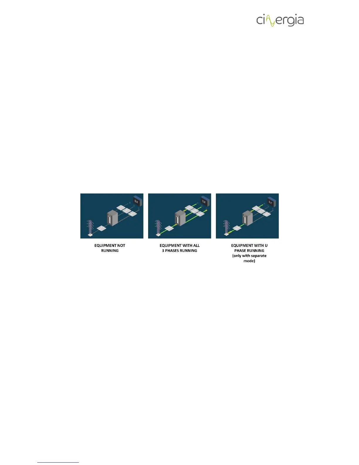
The image in the middle of the Scada tab details the working state of the equipment per phase
using a drawing:
6.3.3. Alarms
The Alarms window displays information about the power supply alarms. Any existing alarm will
appear in this window.