GE+ ACDC Installation and operation manual v11
70 / 121
6.3.2. Scada
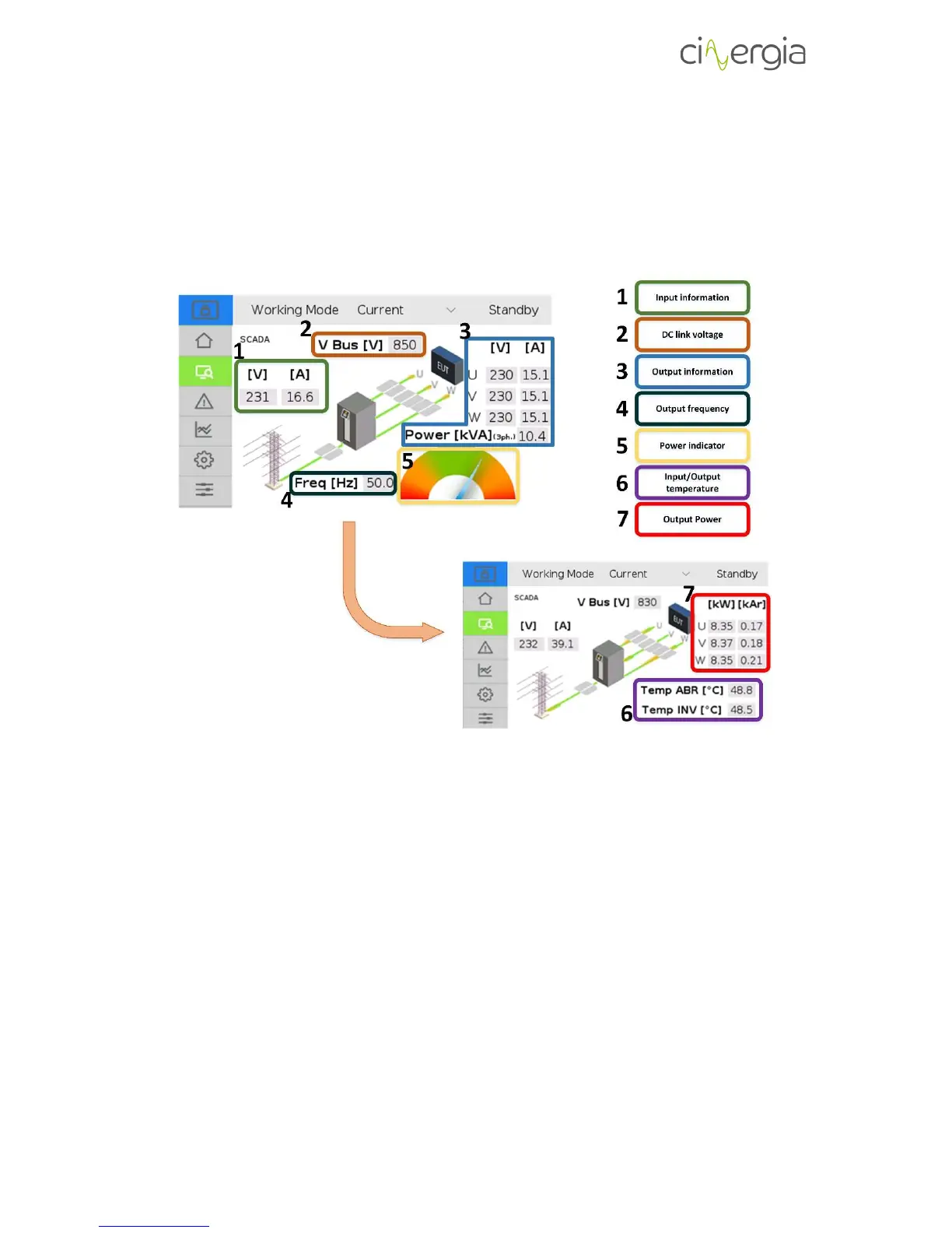
The Scada window is exclusively informative. It shows the main variables of the inverter. The
following schematic points the parts of the window and these points are described below.
1. Input voltage and current. The input voltage of the converter is the three-phase line
voltage whereas the current is the global current flowing in or out the converter.
Remember that the Cinergia equipment is a regenerative supply, so it can work as a
source (delivering current to the EUT side) or as a load (absorbing current from the EUT
side).
2. Voltage in the DC link (bus) of the converter. When the equipment is in Ready state, the
bus will be around 600V and it will be around 800V while being in Run state. Otherwise
it will be decreasing following the discharge curve of the capacitors until it reaches 0V.
3. Output (EUT) voltage, current and power. This part of the tab shows the voltage and
current of each channel and the global power (the addition of all phases).
4. Frequency in the output (EUT) side. If the Cinergia equipment is an AC voltage source,
the output frequency will be chosen within the specified allowed range (10 to 400Hz)
whereas if the equipment is an AC current source, the frequency will be read from the
AC voltage source connected in the EUT side.