GE+ ACDC Installation and operation manual v11
37 / 121
4.4.7. Communications
There are several connectors dedicated to communications, which are listed below:
- (Optional) Connector for RS485/RS232 communications (X11): DB9 connector to be
used when Modbus RS485 option is chosen. It is not possible to have both type of
communication protocols running at the same time.
- (Optional) Connectors for CAN communications (X12): DB9 connectors to be used
when several communications in parallel are required.
- Connector for MODBUS interface (X13): RJ45 connector. A standard Ethernet cable
must be connected between X13 and PC to communicate a remote PC with the grid
emulator. Alternatively, a standard Ethernet cable can be connected between X13 and
a Hub or a Router to communicate a remote PC with the Grid Emulator.
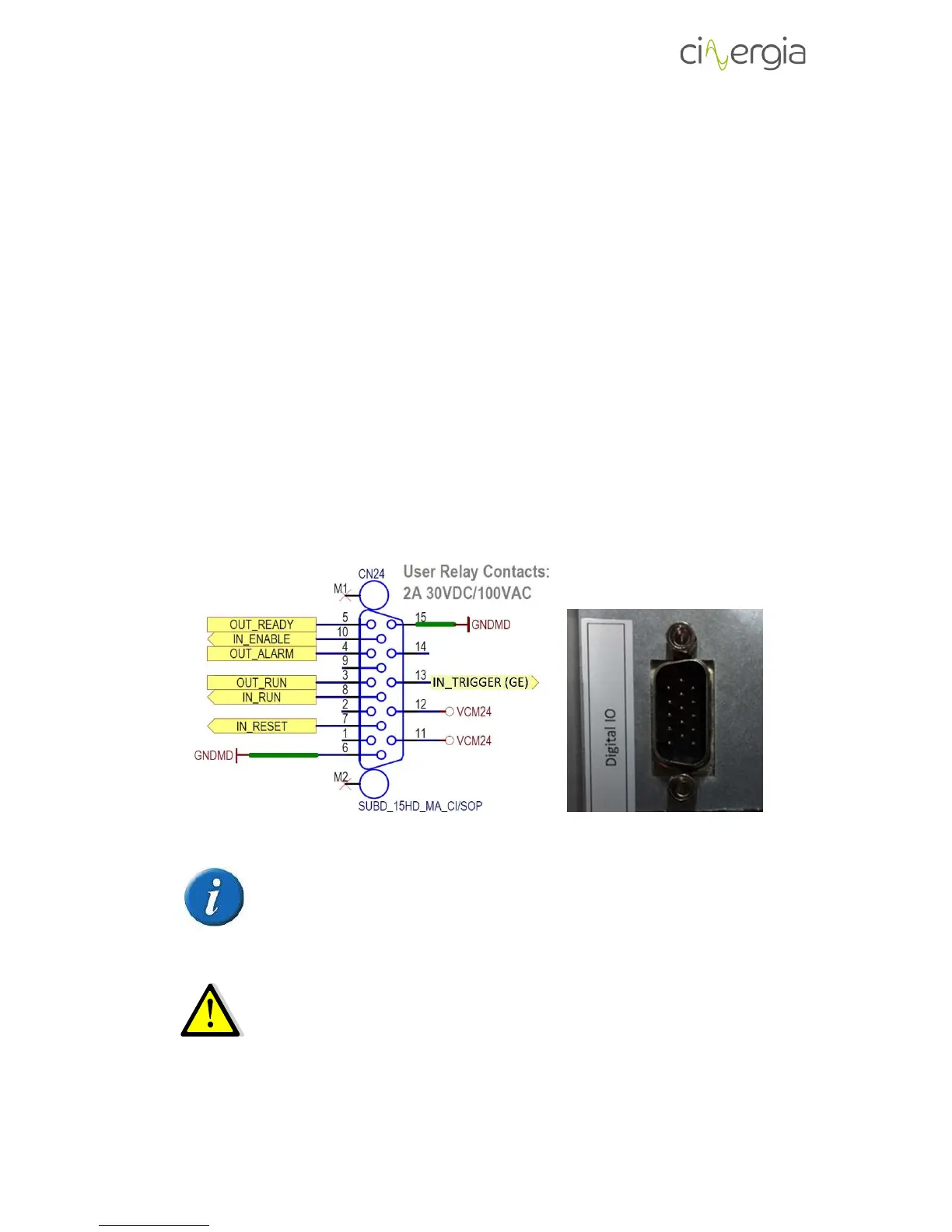
4.4.8. Digital inputs and outputs
Digital inputs and outputs are gathered in X17. All of them are isolated.
Specifically, there are 4 digital inputs which operate at 24V (referenced of GNDMD_RL and
VCM24) and 3 digital outputs (maximum current admitted 8mA). The following scheme shows
the connector with the pinout:
Please note that the connector for digital inputs and outputs of the equipment
is a SUBD_15HD_MA_CI/SOP, MALE CONNECTOR. The necessary connector to
use it is the SUBD_15HD_FA_CI/SOP, FEMALE CONNECTOR.
The maximum admitted input voltage is 24V (REFERENCED TO GNDMD_RL). The
digital outputs are 10V. The maximum admitted output current is 8mA.
The list of each digital functionality is the following: