This feature requires specific network topologies to work properly. The network must have redundant switching
components or other devices that the system is connected to. The following diagrams show examples of a
redundant switching topologies and how the system reacts to various external network device scenarios.
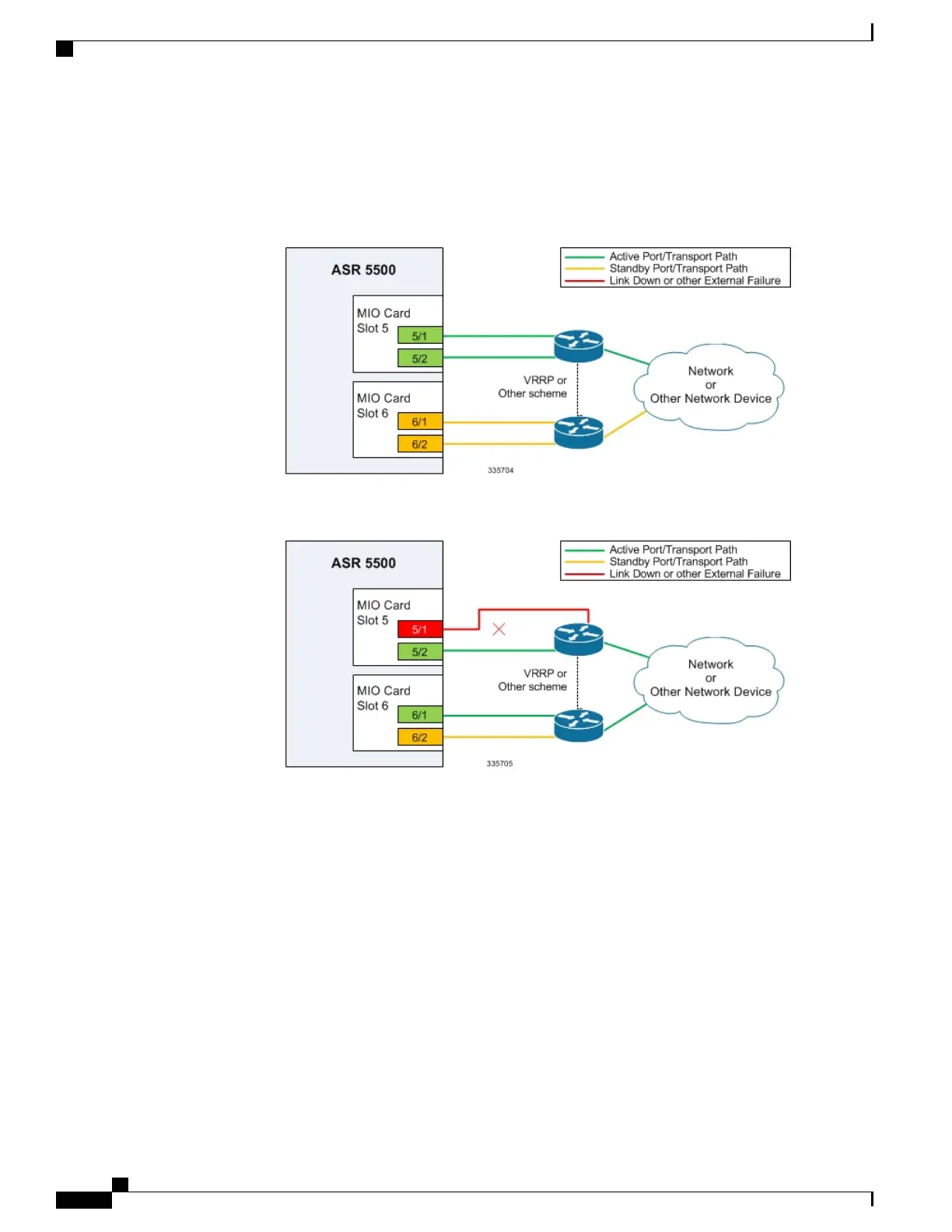
Figure 7: Network Topology Example Using MIO/UMIO Port Redundancy
Figure 8: Port Redundancy Failover in Cable Defect Scenario
In the example above, an Ethernet cable is cut or unplugged, causing the link to go down. When this event
occurs, the system, with port-mode redundancy enabled, recognizes the link down state and makes port 6/1
the active port. The switching device, using some port redundancy scheme, recognizes the failure and enables
ASR 5500 System Administration Guide, StarOS Release 21.4
70
System Settings
Configuring MIO/UMIO/MIO2 Port Redundancy

 Loading...


