SSC System Service LED States
The System Service LED on the SSC illuminates amber to indicate that the system has experienced a hardware
component failure.
This LED is off during normal operation.
The possible states for this LED are described in the following table. If the LED is not green, use the
troubleshooting information in the table to diagnose the problem.
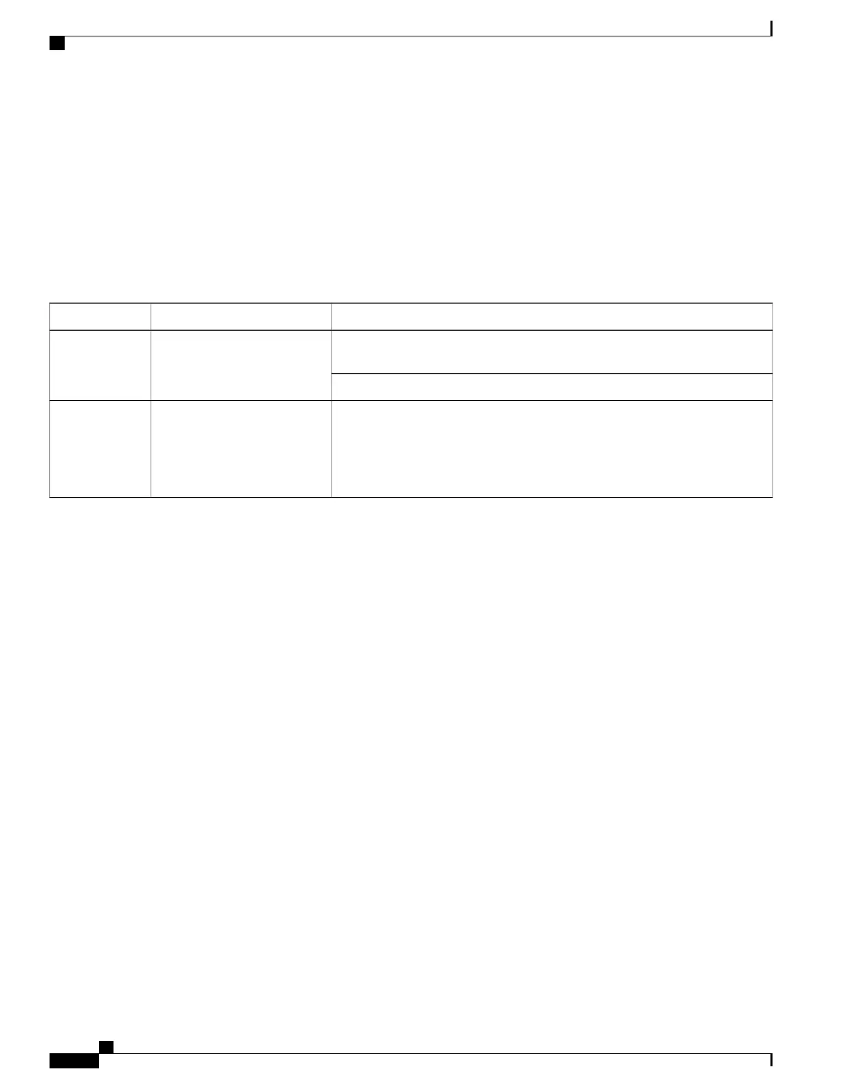
Table 33: SSC System Service LED States 12
TroubleshootingDescriptionColor
Monitoring the System for show commands, the outputs of which will assist in
further determining the problem.
System requires maintenance
(fan filter, temperature warning,
PFU outage etc.).
Amber
Refer to System Logs for information on how to view logs.
No maintenance needed.No component failures have
been detected.
OR
Card is not receiving power.
None
Testing System Alarm Outputs
The system provides the following two physical alarm mechanisms:
•
System Audible Alarm: Located on the SSC, the speaker is used to provide an audible indicator that
a minor, major, or critical alarm has occurred.
•
CO Alarms Interface: Located on the SSC, this interface provides a DB-15 connector that enables
three dry-contact relays (Form C) for the triggering of external audio and/or visual indicators. These
indicators can be used to alert that either a minor, major, or critical alarm has occurred.
The operation of these alarms can be tested by issuing the following command:
[local]host_name# test alarm { audible | central-office [ critical | major | minor ] }
When this command is executed, the specified alarm is activated for a period of 10 seconds. After this time,
the alarm will return to its previous condition.
Taking Corrective Action
In the event that an issue was discovered with an installed application or line card, depending on the severity,
it may be necessary to take corrective action.
The system provides several redundancy and fail-over mechanisms to address issues with application and line
cards in order to minimize system downtime and data loss. These mechanisms are described in the sections
that follow.
ASR 5500 System Administration Guide, StarOS Release 21.4
216
Troubleshooting
Testing System Alarm Outputs

 Loading...


