PIM Shared Tree and Source Tree
By default, members of a group receive data from senders to the group across a single data-distribution tree
rooted at the RP.
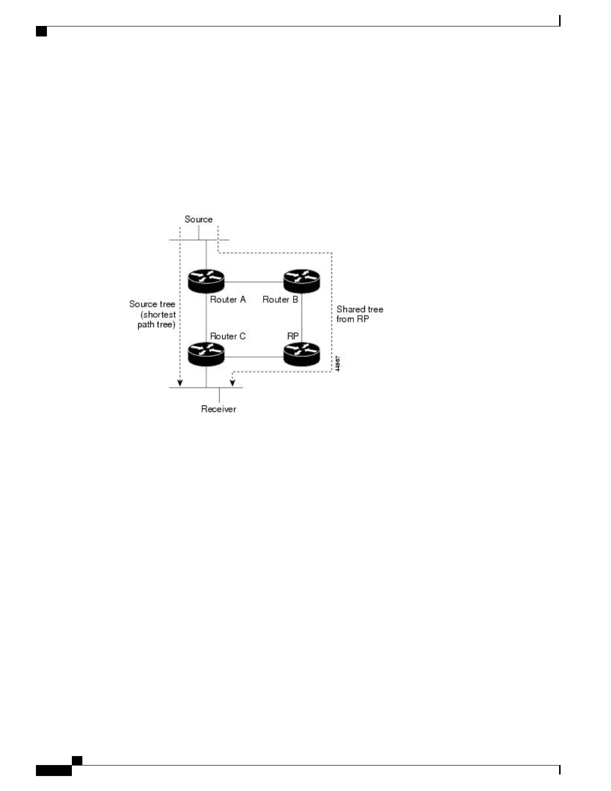
The following figure shows this type of shared-distribution tree. Data from senders is delivered to the RP for
distribution to group members joined to the shared tree.
Figure 4: Shared Tree and Source Tree (Shortest-Path Tree)
If the data rate warrants, leaf routers (routers without any downstream connections) on the shared tree can
use the data distribution tree rooted at the source. This type of distribution tree is called a shortest-path tree
or source tree. By default, the software switches to a source tree upon receiving the first data packet from a
source.
This process describes the move from a shared tree to a source tree:
1
A receiver joins a group; leaf Router C sends a join message toward the RP.
2
The RP puts a link to Router C in its outgoing interface list.
3
A source sends data; Router A encapsulates the data in a register message and sends it to the RP.
4
The RP forwards the data down the shared tree to Router C and sends a join message toward the source.
At this point, data might arrive twice at Router C, once encapsulated and once natively.
5
When data arrives natively (unencapsulated) at the RP, it sends a register-stop message to Router A.
6
By default, reception of the first data packet prompts Router C to send a join message toward the source.
7
When Router C receives data on (S, G), it sends a prune message for the source up the shared tree.
8
The RP deletes the link to Router C from the outgoing interface of (S, G). The RP triggers a prune message
toward the source.
Join and prune messages are sent for sources and RPs. They are sent hop-by-hop and are processed by each
PIM device along the path to the source or RP. Register and register-stop messages are not sent hop-by-hop.
Catalyst 2960-XR Switch IP Multicast Routing Configuration Guide, Cisco IOS Release 15.0(2)EX1
44 OL-29426-01
Configuring PIM
PIM Shared Tree and Source Tree
 Loading...


