1-14
Catalyst 2960 Switch Hardware Installation Guide
OL-7075-09
Chapter 1 Product Overview
Front Panel Description
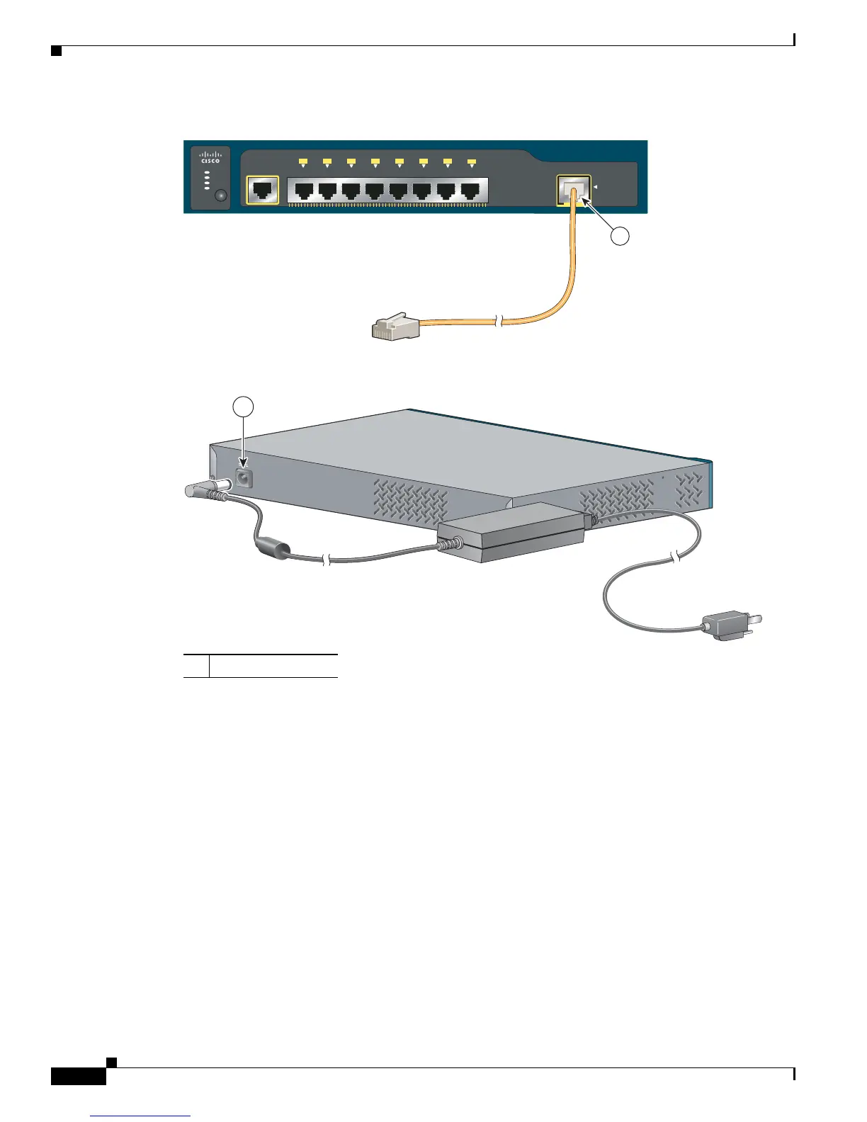
Figure 1-21 Connecting Through a 10/100/1000 Port
Figure 1-22 Connecting Through an External AC Power Adapter
LEDs
You can use the switch LEDs to monitor switch activity and its performance. Figure 1-23 shows the
switch LEDs and the Mode button that you use to select one of the port modes.
All LEDs are visible through the GUI management applications—Network Assistant for multiple
switches and the device manager for a single switch. The switch software configuration guide describes
how to use the CLI to configure and to monitor individual switches and switch clusters.
Only the Catalyst 2960 PoE switches have a PoE LED.
The four Catalyst 2960 8-port switches and these models do not have an RPS connector or an RPS LED:
Catalyst 2960-24-S, Catalyst 2960-24TC-S, Catalyst 2960-48TT-S, Catalyst 2960-48TC-S.
Catalyst 2960 Series
SYST
STAT
DPLX
SPD
MODE
CONSOLE
1
1x 2x 3x 4x 5x 6x 7x
8x
PoE INPUT
204644
1
1 Power adapter port
48V , 0.3 A
1
270433