B-7
Catalyst 2960 Switch Hardware Installation Guide
OL-7075-09
Appendix B Connector and Cable Specifications
Cable and Adapter Specifications
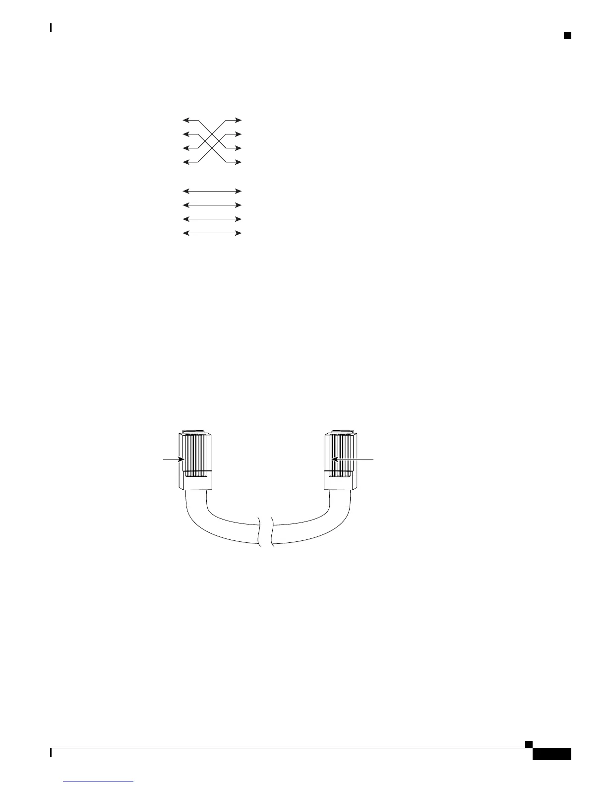
Figure B-8 Four Twisted-Pair Crossover Cable Schematics for 10/100/1000 Ports
Crossover Cable and Adapter Pinouts
This section describes how to identify a crossover cable and also describes the adapter pinouts.
Identifying a Crossover Cable
To identify a crossover cable, compare the two modular ends of the cable. Hold the cable ends
side-by-side, with the tab at the back. The wire connected to the pin on the outside of the left plug should
be a different color from the wire connected to the pin on the inside of the right plug. (See Figure B-9.)
Figure B-9 Identifying a Crossover Cable
1 TP0+
2 TP0-
3 TP1+
6 TP1-
1 TP0+
Switch Switch
2 TP0-
3 TP1+
6 TP1-
4 TP2+
5 TP2-
7 TP3+
8 TP3-
4 TP2+
5 TP2-
7 TP3+
8 TP3-
65274
Pin 1
200915
Pin 1
Pin 1 on one connector and
pin 1 on the other connector
should be different colors.