2-12
Catalyst 2960 Switch Hardware Installation Guide
OL-7075-09
Chapter 2 Switch Installation (24- and 48-Port Switches)
Installing the Switch
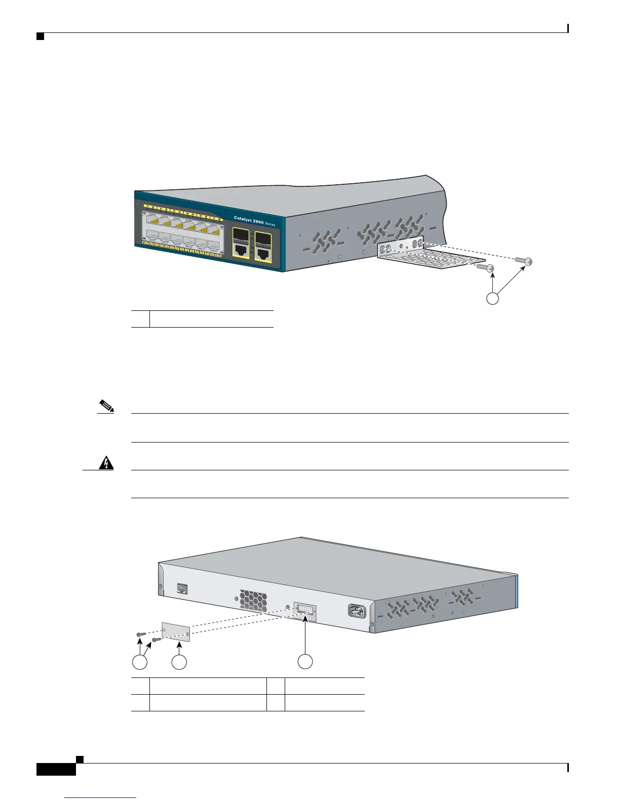
Attaching the Brackets to the Switch for Wall-Mounting
Figure 2-10 shows how to attach a 19-inch bracket to one side of the switch. Follow the same steps to
attach the second bracket to the opposite side.
Figure 2-10 Attaching the 19-inch Brackets for Wall-Mounting
Attaching the RPS Connector Cover
If your switch has an RPS connector and you are not using an RPS with your switch, use the two Phillips
pan-head screws to attach the RPS connector cover to the back of the switch, as shown in Figure 2-11.
Note The Catalyst 2960 8-port switches and the Catalyst 2960-24-S, 2960-24TC-S, 2960-48TT-S, and
2960-48TC-S switches do not have an RPS connector.
Warning
If an RPS is not connected to the switch, install an RPS connector cover on the back of the switch.
Statement 265
Figure 2-11 Attaching the RPS Connector Cover on the Catalyst 2960 Switch
1 Phillips truss-head screws
1 Phillips pan-head screws 3 RPS connector
2 RPS connector cover