B-3
Catalyst 2960 Switch Hardware Installation Guide
OL-7075-09
Appendix B Connector and Cable Specifications
Connector Specifications
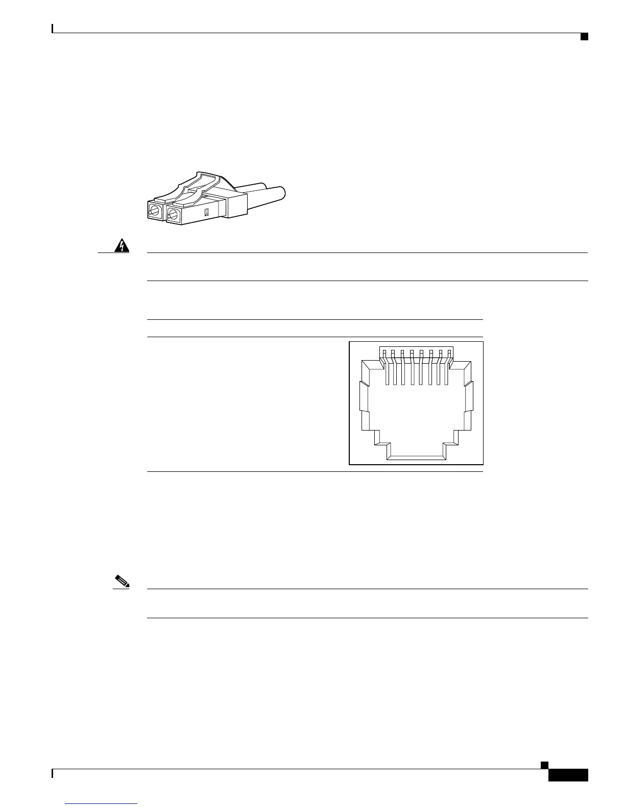
SFP Module Ports
The Catalyst 2960 switch uses SFP modules for fiber-optic and copper uplink ports. See the
Catalyst 2960 switch release notes for a list of supported SFP modules.
Figure B-2 Fiber-Optic SFP Module LC Connector
Warning
Invisible laser radiation may be emitted from disconnected fibers or connectors. Do not stare into
beams or view directly with optical instruments.
Figure B-3 Copper SFP Module RJ-45 Connector
Dual-Purpose Ports
The Ethernet port on a dual-purpose port uses standard RJ-45 connectors. Figure B-4 shows the pinouts.
The SFP module slot on a dual-purpose port uses SFP modules for fiber-optic and copper uplink ports.
See the Catalyst 2960 switch release notes for a list of supported SFP modules.
Note The auto-MDIX feature is enabled by default. For configuration information for this feature, see the
switch software configuration guide or the switch command reference.
60915
231 45678Pin Label
1
2
3
4
5
6
7
8
TP0+
TP0-
TP1+
TP2+
TP2-
TP1-
TP3+
TP3-