Figure 53: Closed and Secured Spring-Loaded Ejectors on the Supervisor Card
Step 7 Tighten the two captive screws using a 3/16" flat-blade torque screwdriver with a torque of 10-12 lb-in (1.12-1.36 Nm)
to secure the card.
What to do next
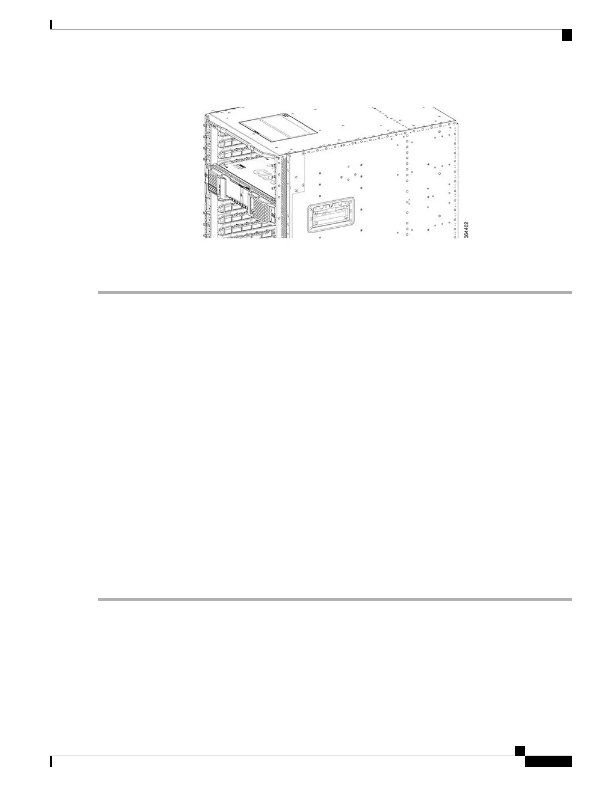
• If you are using a single Supervisor Card, install a blank card for the Supervisor in the empty slot.
• Connect memory stick or flash drive to use the USB port (if required).
• Connect cable to use the console port (if required).
Using the SFP+ Ports on the Supervisor PIC
Before you begin
• Install the Supervisor PIC.
• Install the SFP+ module in the Supervisor PIC
• Install the Supervisor Card.
• Do not remove the protective dust plugs on the unplugged fiber-optic cable connectors and the SFP+
optical bores until you are ready to make a connection.
Required Tools and Equipment
• Fiber-optic cable with the LC connector
Step 1 Remove the dust plugs from the network interface cable LC connectors. Save the dust plugs for future use.
Step 2 Inspect and clean the LC connector end-faces.
Step 3 Remove the dust plug from the SFP+ module optical bores on the Supervisor PIC.
Step 4 Immediately connect the fiber-optic cable with cable LC connector to the SFP+ port.
Grasp the LC connector housing to connect the fiber-optic cable to the SFP+ ports.
Important
Cisco Converged Broadband Routers Hardware Installation Guide
97
Installing the Supervisor in the Cisco cBR Chassis
Using the SFP+ Ports on the Supervisor PIC

 Loading...


