EasyManuals Logo

Cisco cBR Series Hardware Installation Guide

Cisco cBR Series
270 pages
To Next Page IconTo Next Page
To Previous Page IconTo Previous Page
Page #106 background imageLoading...
Page #106 background image
Figure 54: LC fiber-optic connector
What to do next
Route the fiber-optic cables through the Supervisor PIC cable management bracket and chassis-mounted
fiber/cable routing guide.
Using the DTI Ports on the Supervisor PIC
Before you begin
Install the Supervisor PIC.
Install the Supervisor Card.
Required Tools and Equipment
RJ-45 cable
Clock source (DTI server)
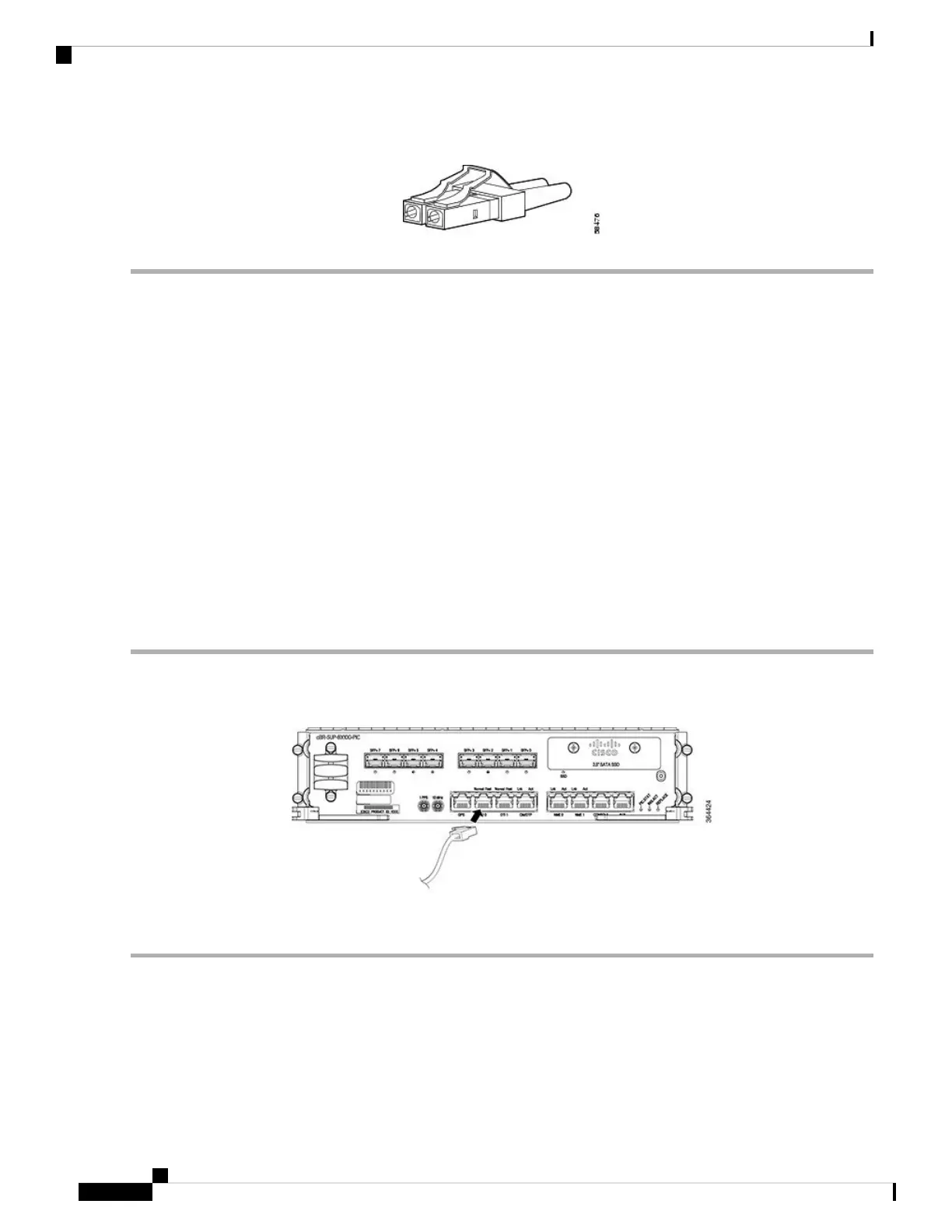
Step 1 Connect one end of the RJ-45 cable to the DTI port on the Supervisor PIC.
Figure 55: DTI Port Connection on the Supervisor PIC
Step 2 Connect the other end of the RJ-45 cable to the to the DTI server as a reference clock source.
What to do next
Route the RJ-45 cable through the Supervisor PIC cable management bracket and chassis-mounted fiber/cable
routing guide.
Cisco Converged Broadband Routers Hardware Installation Guide
98
Installing the Supervisor in the Cisco cBR Chassis
Using the DTI Ports on the Supervisor PIC

Table of Contents

Other manuals for Cisco cBR Series

Questions and Answers:

Question and Answer IconNeed help?

Do you have a question about the Cisco cBR Series and is the answer not in the manual?

Cisco cBR Series Specifications

General IconGeneral
CategoryNetwork Router
Modular DesignYes
Operating SystemCisco IOS XE
Model ExamplescBR-8, cBR-4
Product SeriescBR Series
PurposeConverged Broadband Router
DOCSIS SupportDOCSIS 3.1
RedundancyYes
ManagementCisco Prime
Product FamilycBR Series
Downstream Frequency RangeUp to 1.2 GHz
Upstream Frequency RangeUp to 204 MHz
Modulation SchemesQAM
Power SupplyRedundant AC or DC power supplies
Operating Temperature0°C to 40°C
Storage Temperature-40°C to 70°C
Humidity5 to 95% noncondensing

Related product manuals