Step 2 Align the guide pins below the cLGA connector with the guide holes in the PCB and set the cLGA connector on the PCB.
Step 3 Insert the 10830 cap-screws into the and tighten using the hex socket driver with a torque of 4.4 lb-inch (0.5 Nm).
What to do next
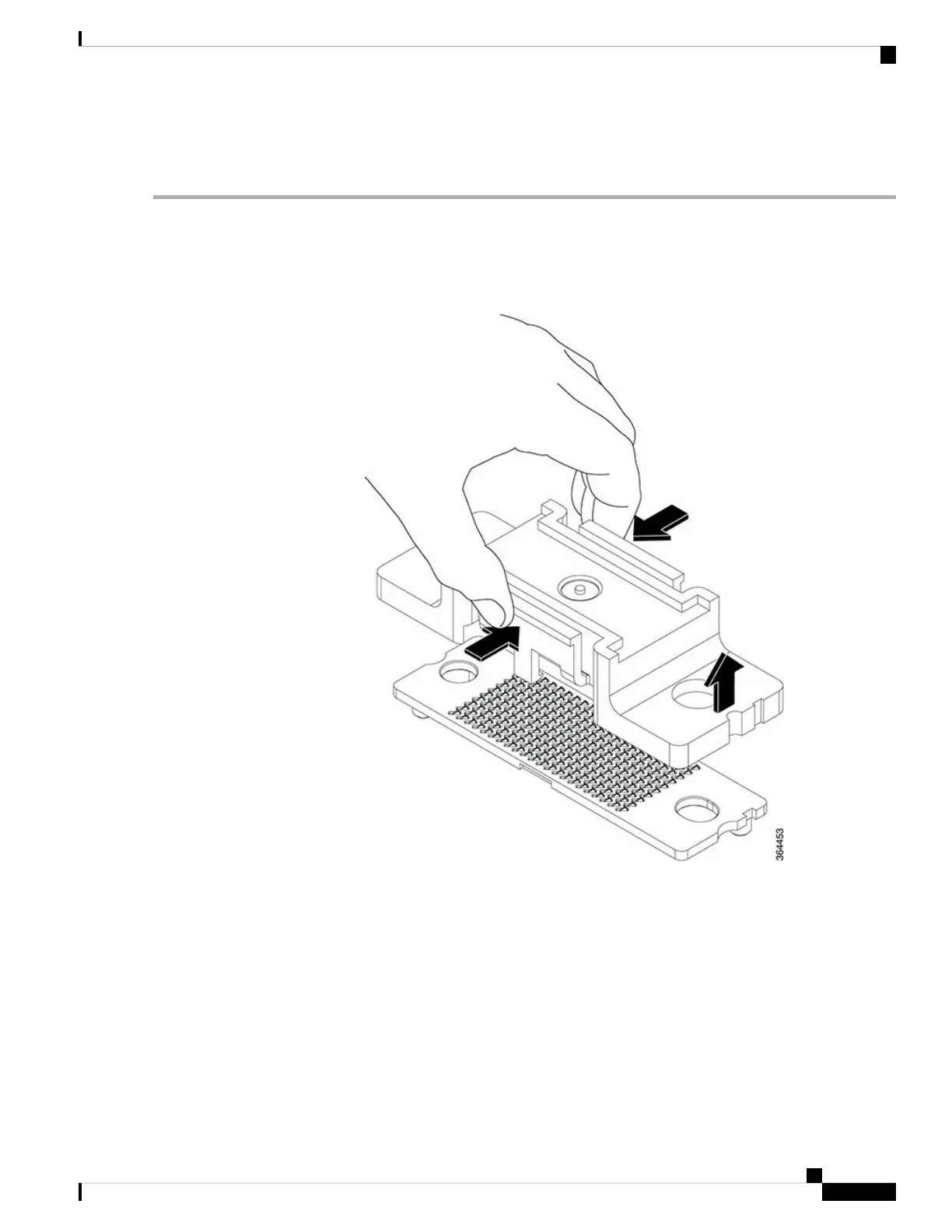
• Remove the protective cover from the cLGA connector before the Downstream D3.0 Module is installed.
Figure 146: Removing the Protective Cover from the cLGA Connector
• Install the Downstream D3.0 Module.
Maintaining the DOCSIS MAC Interface and PIC Card
Removing the DOCSIS MAC Interface Line Card from the Cisco cBR Chassis
It is not necessary to power down the chassis to remove an DOCSIS MAC interface line card.
Cisco Converged Broadband Routers Hardware Installation Guide
223
Maintaining the Interface Cards in the Cisco cBR Chassis
Maintaining the DOCSIS MAC Interface and PIC Card

 Loading...


