• Be aware of the weight and size of the equipment. Handle it with care.
Restrictions
• Install the interface line card in the slot corresponding to the RF Protect or RF Through PIC installed.
Required Tools and Equipment
• ESD-preventive wrist strap
• 3/16" flat-blade torque screwdriver
• One of the following SSI Cards (line cards):
• DOCSIS 3.0 MAC/PHY line card [PID: CBR-LC-8D30-16U30]
• DOCSIS 3.1 MAC/PHY line card [PID: CBR-LC-8D31-16U31, or CBR-LC-4D31-16U31]
• Line card blank. [PID: CBR-LC-BLANK]
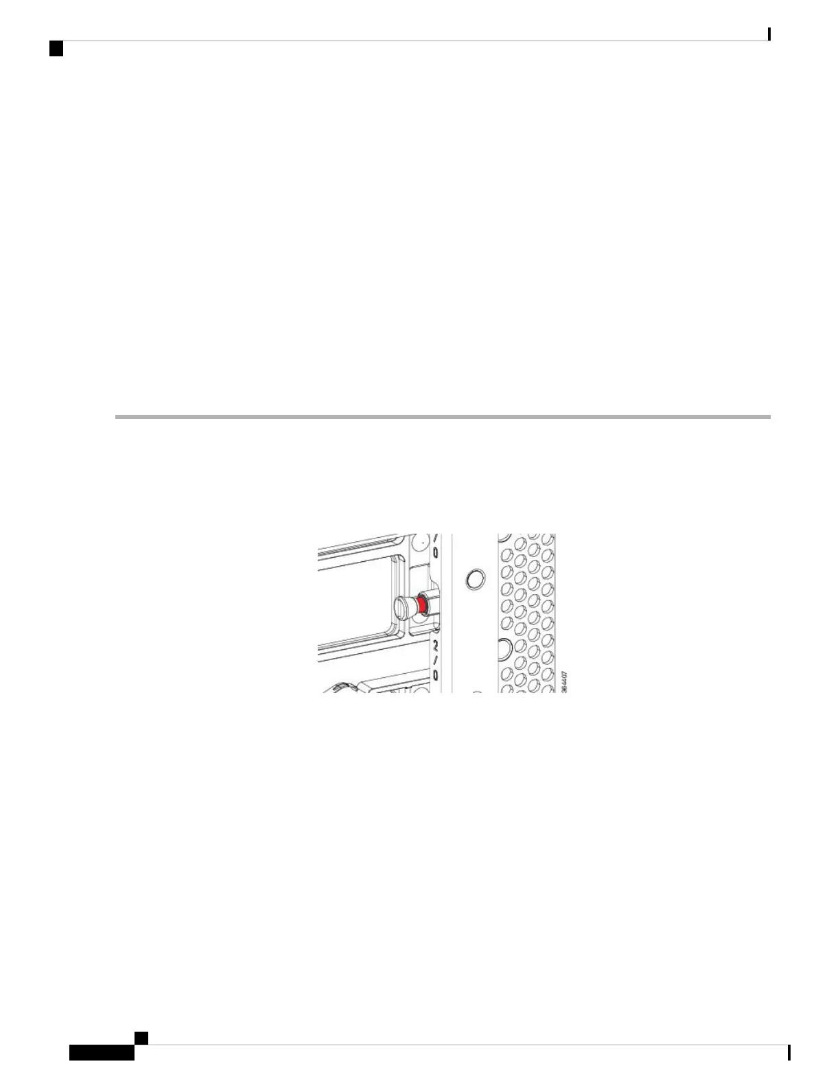
Step 1 Loosen the captive screws on the appropriate slot using a 3/16" flat-blade torque screwdriver until the red bands are
visible on the captive screws.
Ensure that the red band on the screws are visible.
Note
Figure 102: Red Band on the Screw
Step 2 Pull the spring-loaded ejectors on the card until they release and are perpendicular to the faceplate.
Cisco Converged Broadband Routers Hardware Installation Guide
146
Installing the Interface Line and PIC Cards
Installing the DOCSIS MAC/PHY Interface Line Card in the Cisco cBR Chassis

 Loading...


