EasyManuals Logo

Cisco cBR Series Hardware Installation Guide

Cisco cBR Series
270 pages
To Next Page IconTo Next Page
To Previous Page IconTo Previous Page
Page #159 background imageLoading...
Page #159 background image
Step 2 Carefully align the PIC with the plastic guides in the slot.
Step 3 Slide the PIC into the slot applying even pressure using both your hands until it is within an inch of full insertion.
Step 4 Open the ejector levers on the PIC and fully insert the PIC into the slot applying even pressure on both sides until it mates
with the midplane connectors.
To prevent damage to the midplane connector, do not use excessive force when inserting the card into the slot.
Caution
While installing a PIC Blank card, open the ejector levers and fully insert the PIC blank into the slot until the
ejectors touch the chassis flanges.
Note
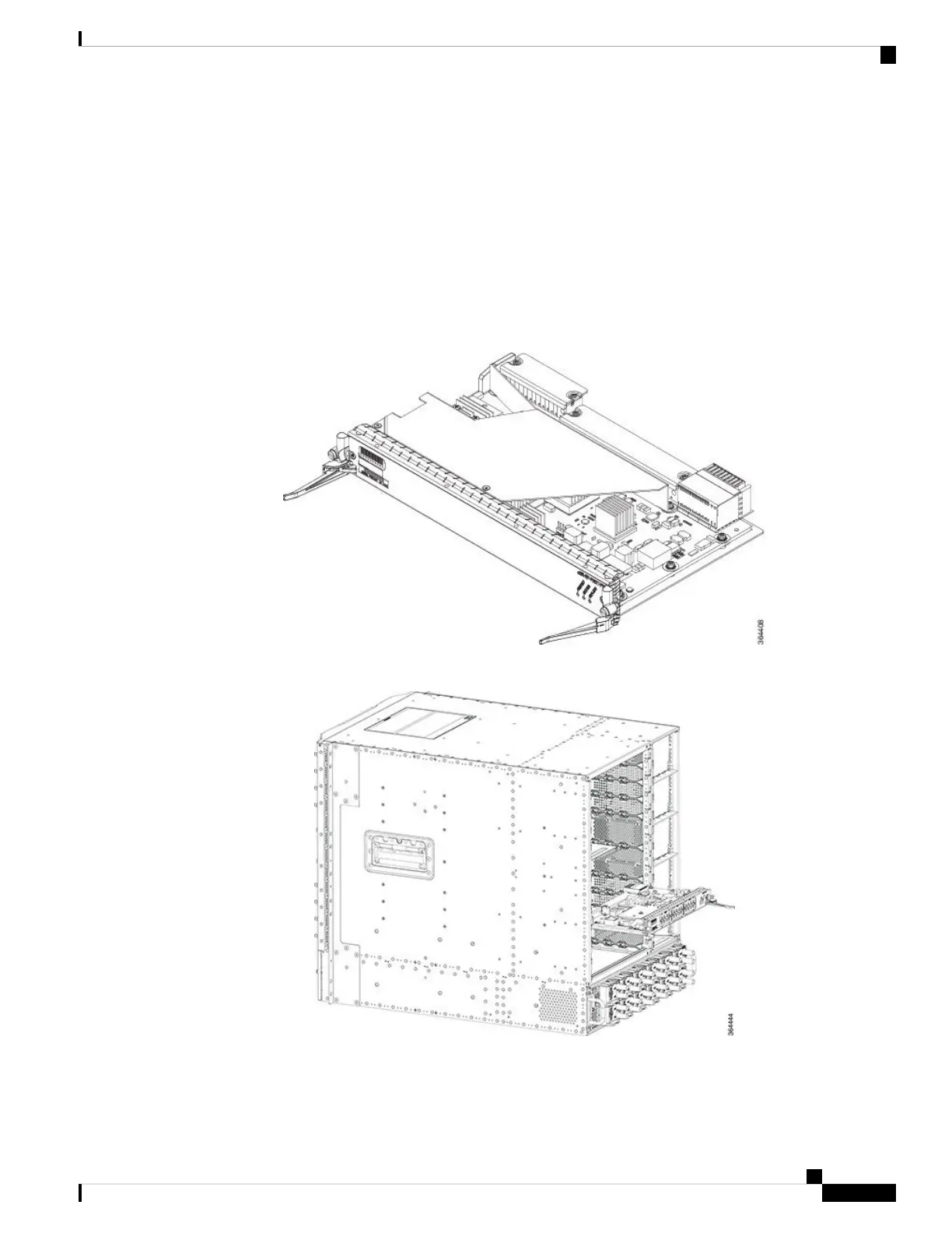
Figure 107: Opening the Ejector Levers on the PIC
Figure 108: Inserting the PIC
Step 5 Simultaneously pivot both the ejector levers towards each other until they cannot be pivoted any further.
Cisco Converged Broadband Routers Hardware Installation Guide
151
Installing the Interface Line and PIC Cards
Installing Digital PIC in the Cisco cBR Chassis

Table of Contents

Other manuals for Cisco cBR Series

Questions and Answers:

Question and Answer IconNeed help?

Do you have a question about the Cisco cBR Series and is the answer not in the manual?

Cisco cBR Series Specifications

General IconGeneral
CategoryNetwork Router
Modular DesignYes
Operating SystemCisco IOS XE
Model ExamplescBR-8, cBR-4
Product SeriescBR Series
PurposeConverged Broadband Router
DOCSIS SupportDOCSIS 3.1
RedundancyYes
ManagementCisco Prime
Product FamilycBR Series
Downstream Frequency RangeUp to 1.2 GHz
Upstream Frequency RangeUp to 204 MHz
Modulation SchemesQAM
Power SupplyRedundant AC or DC power supplies
Operating Temperature0°C to 40°C
Storage Temperature-40°C to 70°C
Humidity5 to 95% noncondensing

Related product manuals