• For the AC-powered Cisco cBR with 1+1 redundancy, ensure that the chassis has six operational AC
Power Modules for the chassis to be functional.
Required Tools and Equipment
• ESD-preventive wrist strap
• 3/16" flat-blade torque screwdriver
• Antistatic bag
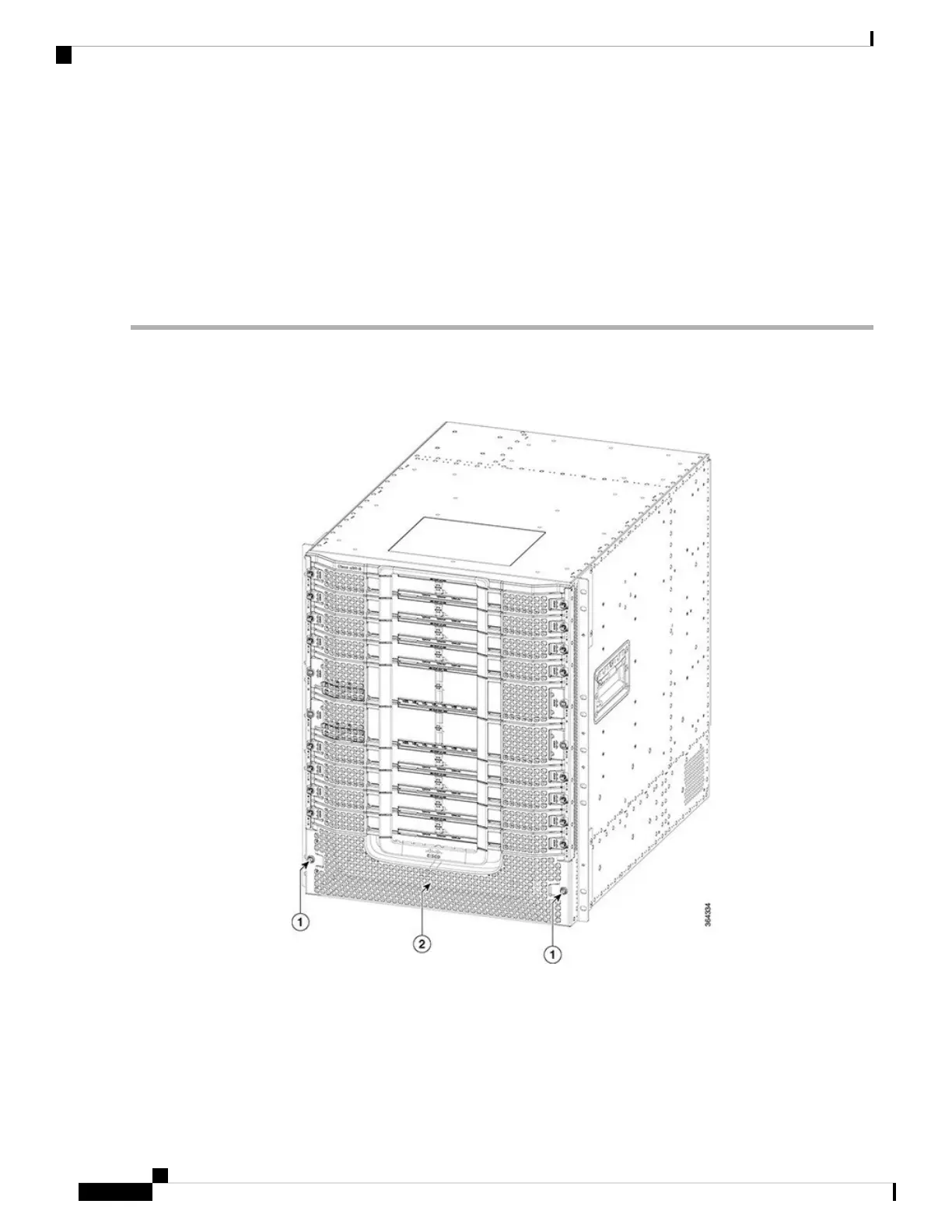
Step 1 Loosen the two screws on the front power entry bezel using a 3/16" flat-blade torque screwdriver. Remove the front
power entry bezel from the chassis.
Figure 118: Removing the Front Power Entry Bezel from the Chassis
Step 2 Loosen the screw on the Power Module using a 3/16" flat-blade torque screwdriver.
Step 3 Pull the handle down to disengage the Power Module from the chassis.
Step 4 Slide the Power Module out of its bay with one hand while supporting the base of the module with your other hand.
Cisco Converged Broadband Routers Hardware Installation Guide
192
Maintaining the Power System in the Cisco cBR Chassis
Removing the Power Module from the Cisco cBR Chassis
 Loading...


