EasyManuals Logo

Cisco cBR Series Hardware Installation Guide

Cisco cBR Series
270 pages
To Next Page IconTo Next Page
To Previous Page IconTo Previous Page
Page #229 background imageLoading...
Page #229 background image
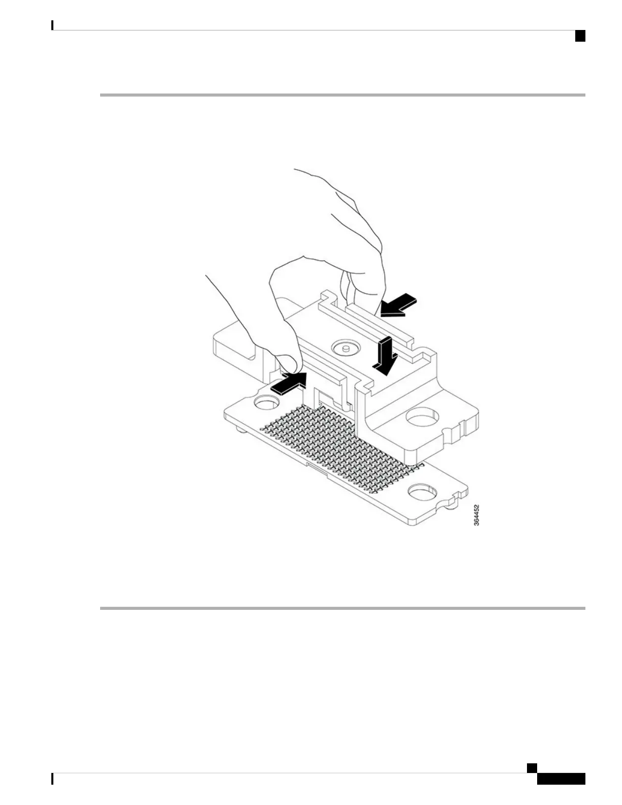
Step 1 Replace the protective cover on the cLGA connector by pinching the side clamps on the cover with your thumb and index
finger and placing the cover in the cLGA connector and releasing the clamps. Ensure the clamp locks on the cLGA
connector.
Figure 144: Installing the Protective Cover on the cLGA Connector
Step 2 Loosen and remove the two 10830 cap-screws that fasten the cLGA connector to the PCB.
Step 3 Hold the cLGA connector with protective cover using your thumb and index finger. Lift the cLGA connector up until
the guide pins at the bottom of the cLGA connector are removed from the guide holes in the PCB.
Step 4 Place the cLGA connector in an antistatic bag.
What to do next
Install a replacement cLGA Connector.
Cisco Converged Broadband Routers Hardware Installation Guide
221
Maintaining the Interface Cards in the Cisco cBR Chassis
Removing the cLGA Connector from an Interface Line Card

Table of Contents

Other manuals for Cisco cBR Series

Questions and Answers:

Question and Answer IconNeed help?

Do you have a question about the Cisco cBR Series and is the answer not in the manual?

Cisco cBR Series Specifications

General IconGeneral
CategoryNetwork Router
Modular DesignYes
Operating SystemCisco IOS XE
Model ExamplescBR-8, cBR-4
Product SeriescBR Series
PurposeConverged Broadband Router
DOCSIS SupportDOCSIS 3.1
RedundancyYes
ManagementCisco Prime
Product FamilycBR Series
Downstream Frequency RangeUp to 1.2 GHz
Upstream Frequency RangeUp to 204 MHz
Modulation SchemesQAM
Power SupplyRedundant AC or DC power supplies
Operating Temperature0°C to 40°C
Storage Temperature-40°C to 70°C
Humidity5 to 95% noncondensing

Related product manuals