After removing the PIC or a PIC Blank from an operational chassis, install the
replacement PIC or blank PIC in the chassis within three minutes to avoid critical
thermal alarms relating to overheating of individual components.
Caution
• Attach an ESD-preventive wrist strap to your wrist and connect the other end to the grounding lug
connected to the chassis.
• Be aware of the weight and size of the equipment. Handle it with care.
Required Tools and Equipments
• ESD-preventive wrist strap
• 3/16" flat-blade screwdriver
• Antistatic bag
Step 1 Loosen the captive screws on the appropriate slot using a 3/16" flat-blade torque screwdriver until the red bands are
visible on the captive screws.
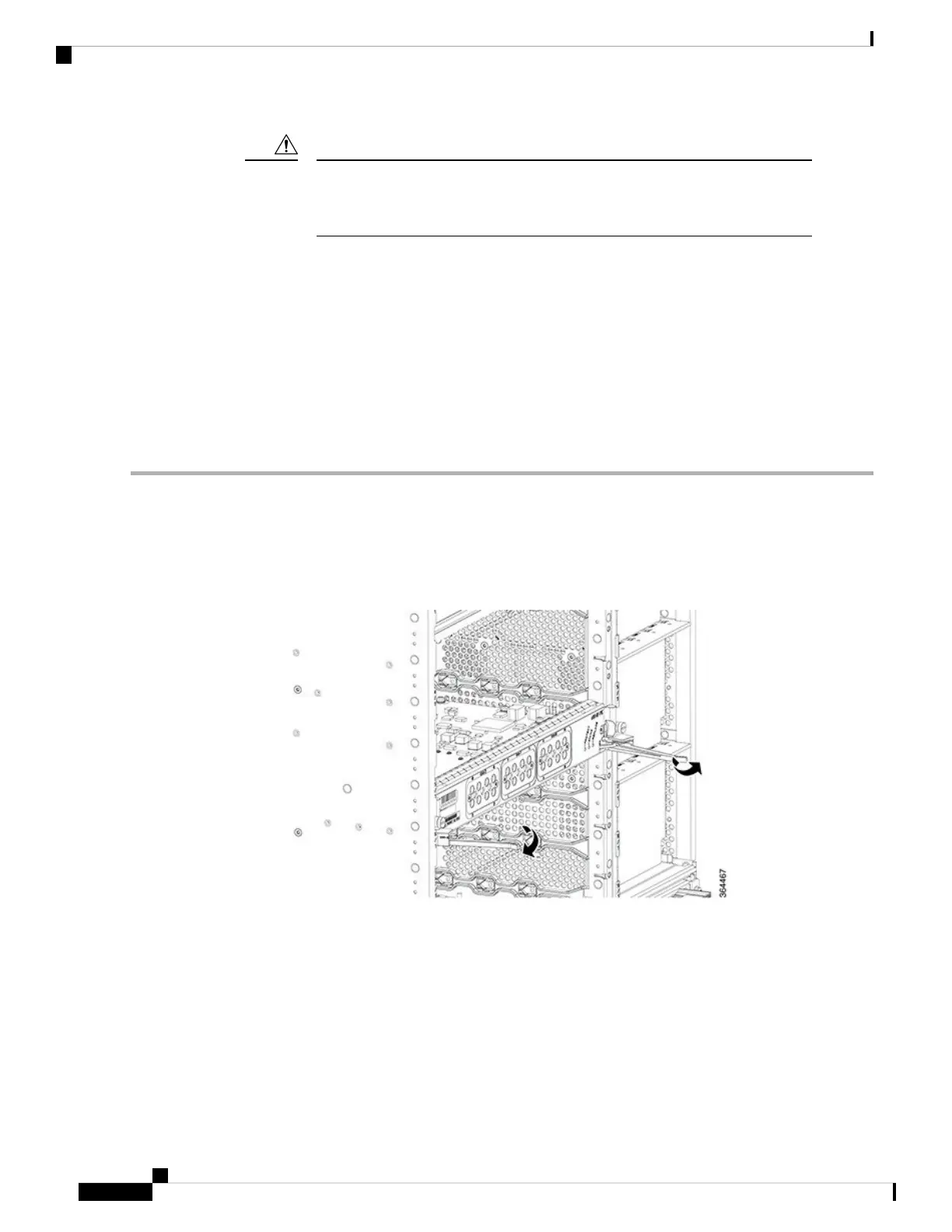
Step 2 Pull the ejectors levers until the PIC is disengaged from the connectors on the midplane. Carefully slide the PIC out of
the slot applying even pressure using both your hands.
Figure 149: Opening the Ejector Levers of the PIC
Cisco Converged Broadband Routers Hardware Installation Guide
226
Maintaining the Interface Cards in the Cisco cBR Chassis
Removing the Digital PIC from the Cisco cBR Chassis

 Loading...


