ValueUnit
10.08 in (25.6 cm)
Depth
17.45 in (44.32 cm)Width
3.85 in (9.78 cm)Height
15 lb (6.8 kg)Maximum weight
Both AC and DC FPEMs have a power switch to enable power to the entire Cisco cBR chassis.
The AC FPEM has the following LED:
• POWER ENABLE—Power status LED
The DC FPEM has the following LEDs:
• POWER ENABLE—Power status LED
• DC PRESENT—Input DC power status LED for each terminal block
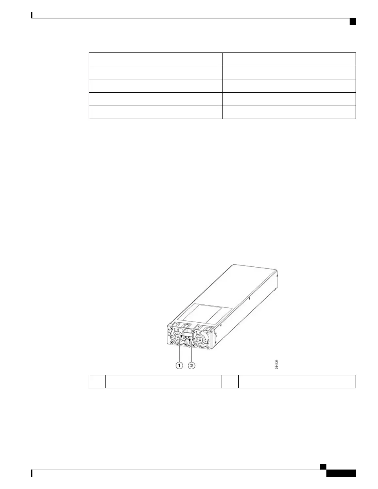
Power Module
The Power Modules provide the power conversion, filtering, and conditioning from facility input power to
the required -52 V midplane power that is used within the chassis. Both AC and DC Power Modules are
available depending on the facility input voltage. These modules have internal fans for cooling.
The Power Modules are installed in the front of the Cisco cBR chassis.
Figure 21: AC Power Module
Screw2Handle1
Cisco Converged Broadband Routers Hardware Installation Guide
37
What is a Cisco cBR Series Converged Broadband Router
Power System

 Loading...


