• Crimping tool for the ground lug
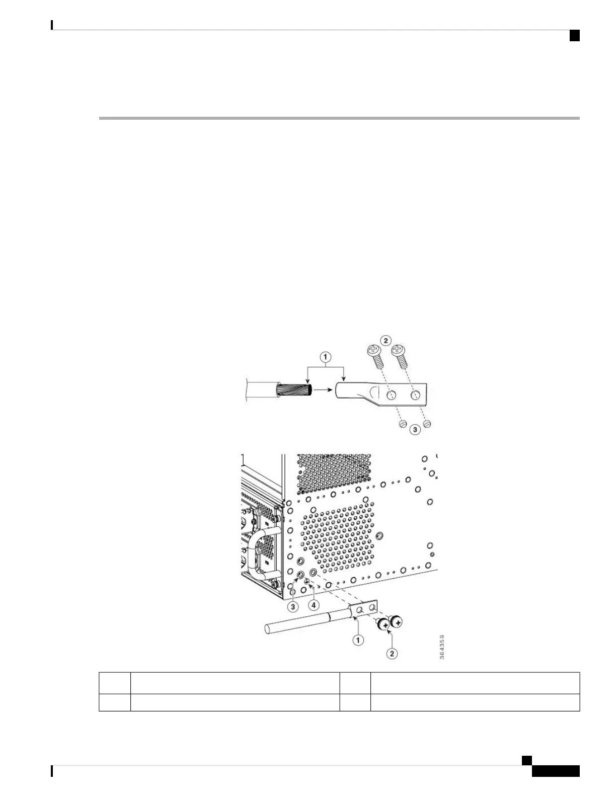
Step 1 Use the wire stripper to strip one end of the AWG #4 wire approximately 1.12 inches (28.4 mm).
Step 2 Insert the AWG #4 wire into the wire receptacle on the grounding lug.
Step 3 Use the crimping tool to carefully crimp the wire receptacle around the wire; this step is required to ensure a proper
mechanical connection.
Step 4 Locate the chassis ground area on the rear lower left-side panel of your chassis.
Step 5 Insert the two ¼-20 screws (available in the accessory kit) through the holes in the grounding lug, and tighten until the
grounding lug is held firmly to the chassis.
The captive nuts are available on the rear lower left side of the chassis for attaching a two-hole ground lug. In
addition, three nuts are available for attaching, so that you can mount the lug horizontally or vertically depending
on the wire routing preferences.
Note
Step 6 Connect the opposite end of the grounding wire to the appropriate grounding point at your site to ensure an adequate
chassis ground.
Figure 35: Chassis Ground Connection
Earth ground lug holes on the chassis3Chassis earth ground lug and lead wire1
Earth ground symbol4¼-20 Grounding screws2
Cisco Converged Broadband Routers Hardware Installation Guide
71
Installing the Cisco cBR Chassis
Attaching a Chassis Ground Connection

 Loading...


