EasyManuals Logo

Cisco cBR Series Hardware Installation Guide

Cisco cBR Series
270 pages
To Next Page IconTo Next Page
To Previous Page IconTo Previous Page
Page #86 background imageLoading...
Page #86 background image
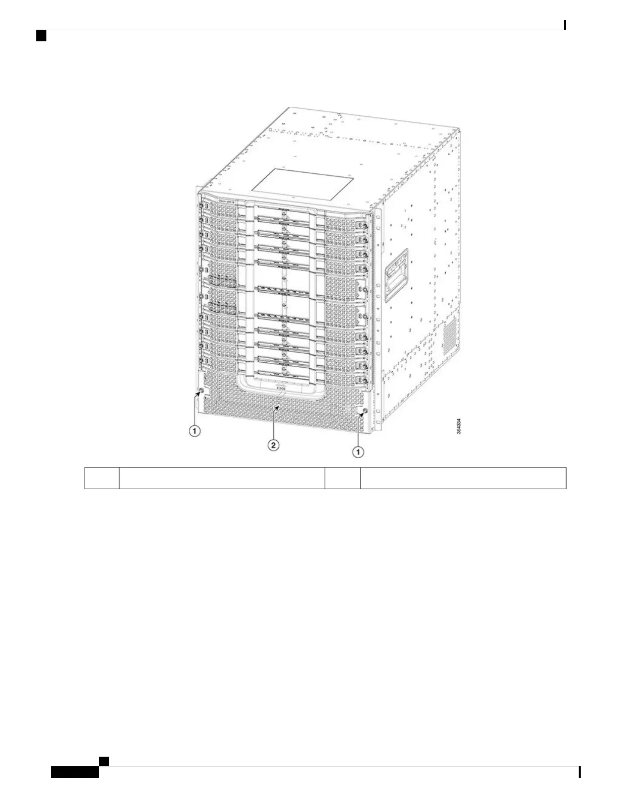
Figure 38: Removing the Front Power Entry Bezel from the Chassis
Front power entry bezel2Screw1
Step 2 Remove the four #6-32 Torx-head screws located on the chassis mounting flanges using a T10 Torx torque screwdriver.
Step 3 Slide the Power Cassette Module into the slot in the chassis until the mounting flanges are fully seated.
Cisco Converged Broadband Routers Hardware Installation Guide
78
Installing the Power System in the Cisco cBR Chassis
Installing the Power Cassette Module in the Cisco cBR Chassis

Table of Contents

Other manuals for Cisco cBR Series

Questions and Answers:

Question and Answer IconNeed help?

Do you have a question about the Cisco cBR Series and is the answer not in the manual?

Cisco cBR Series Specifications

General IconGeneral
CategoryNetwork Router
Modular DesignYes
Operating SystemCisco IOS XE
Model ExamplescBR-8, cBR-4
Product SeriescBR Series
PurposeConverged Broadband Router
DOCSIS SupportDOCSIS 3.1
RedundancyYes
ManagementCisco Prime
Product FamilycBR Series
Downstream Frequency RangeUp to 1.2 GHz
Upstream Frequency RangeUp to 204 MHz
Modulation SchemesQAM
Power SupplyRedundant AC or DC power supplies
Operating Temperature0°C to 40°C
Storage Temperature-40°C to 70°C
Humidity5 to 95% noncondensing

Related product manuals