EasyManuals Logo

Cisco cBR Series Hardware Installation Guide

Cisco cBR Series
270 pages
To Next Page IconTo Next Page
To Previous Page IconTo Previous Page
Page #90 background image
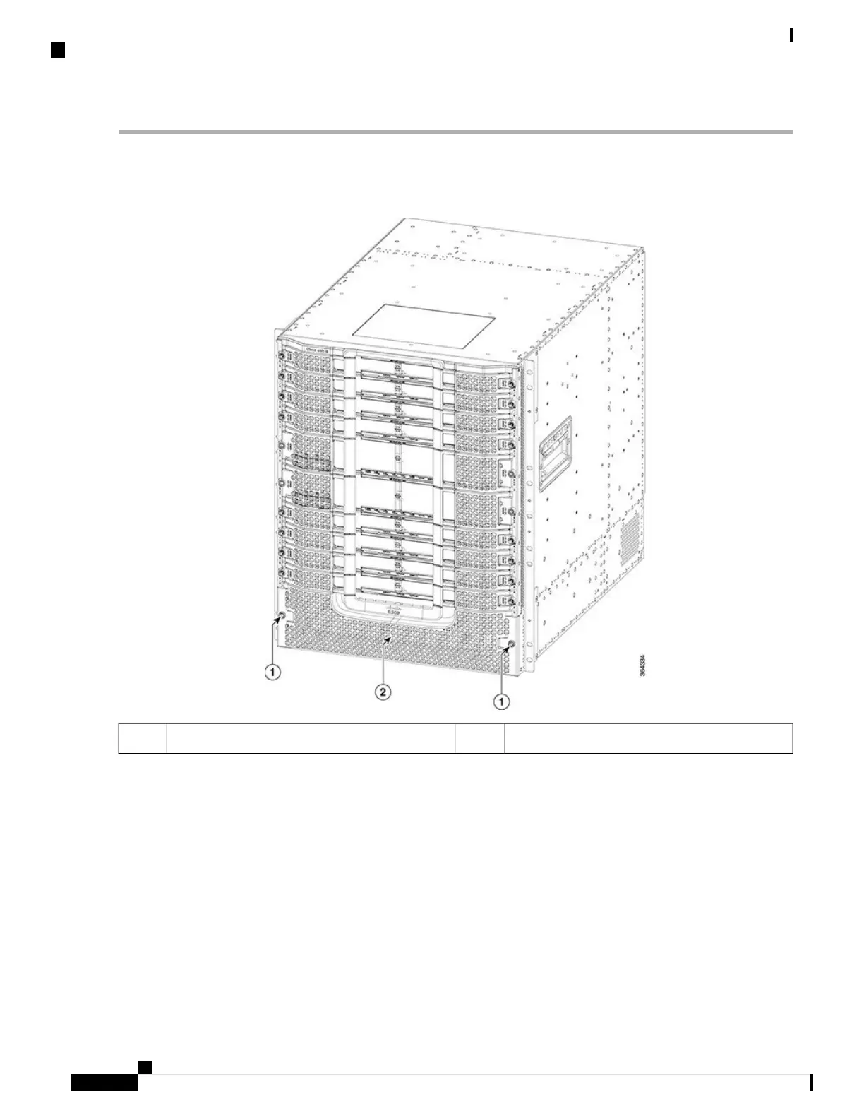
Step 1 Loosen the two screws on the front power entry bezel using a 3/16" flat-blade torque screwdriver. Remove the front
power entry bezel from the chassis.
Figure 41: Removing the Front Power Entry Bezel from the Chassis
Front power entry bezel2Screw1
Step 2 Carefully slide Power Module into the bay until it mates with the FPEM connectors.
To prevent damage to the FPEM connectors, do not use excessive force when inserting the Power Module into
the bay.
Caution
Cisco Converged Broadband Routers Hardware Installation Guide
82
Installing the Power System in the Cisco cBR Chassis
Installing the Power Module in the Cisco cBR Chassis

Table of Contents

Other manuals for Cisco cBR Series

Questions and Answers:

Question and Answer IconNeed help?

Do you have a question about the Cisco cBR Series and is the answer not in the manual?

Cisco cBR Series Specifications

General IconGeneral
CategoryNetwork Router
Modular DesignYes
Operating SystemCisco IOS XE
Model ExamplescBR-8, cBR-4
Product SeriescBR Series
PurposeConverged Broadband Router
DOCSIS SupportDOCSIS 3.1
RedundancyYes
ManagementCisco Prime
Product FamilycBR Series
Downstream Frequency RangeUp to 1.2 GHz
Upstream Frequency RangeUp to 204 MHz
Modulation SchemesQAM
Power SupplyRedundant AC or DC power supplies
Operating Temperature0°C to 40°C
Storage Temperature-40°C to 70°C
Humidity5 to 95% noncondensing

Related product manuals