In the Cisco cBR-8 router,
• Slot 4/1 for the Supervisor PIC corresponds to slot SUP0 for the Supervisor
Card.
• Slot 5/1 for the Supervisor PIC corresponds to slot SUP1 for the Supervisor
Card.
Note
Required Tools and Equipment
• ESD-preventive wrist strap
• Supervisor PIC or blank PIC for the Supervisor
• 3/16" flat-blade torque screwdriver
Step 1 Grasp the faceplate of the PIC with one hand and place your other hand under the PIC to support its weight.
Step 2 Carefully align the PIC with the plastic guides in the slot.
Step 3 Slide the PIC into the slot applying even pressure using both your hands until it is within an inch of full insertion.
Step 4 Open the ejector levers and fully insert the PIC into the slot applying even pressure on both sides until it mates with the
midplane connectors.
To prevent damage to the midplane connectors, do not use excessive force when inserting the PIC into the slot.
Caution
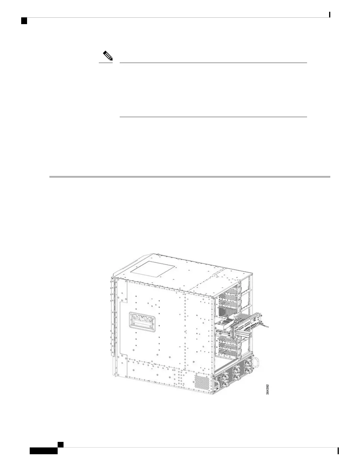
Figure 45: Inserting the Supervisor PIC into the Chassis
Step 5 Simultaneously pivot both the ejector levers towards each other until they cannot be pivoted any further.
Cisco Converged Broadband Routers Hardware Installation Guide
90
Installing the Supervisor in the Cisco cBR Chassis
Installing the Supervisor PIC in the Cisco cBR Chassis

 Loading...


