THE SMART SOLUTION FOR ENERGY EFFICIENCY
MPC MultiProtoCol DDC Controls
November 19, 2018
16
Equipment Touch Mounting Details
Wiring and Mounting the Equipment Touch
1. Remove the backplate from the Equipment Touch:
a. Hold the Equipment Touch as shown in the
image below.
b. While rmly pressing the two tabs on top of
the Equipment Touch, pull on the back-
plate with your index nger untill the back-
plate releases from the Equipment Touch.
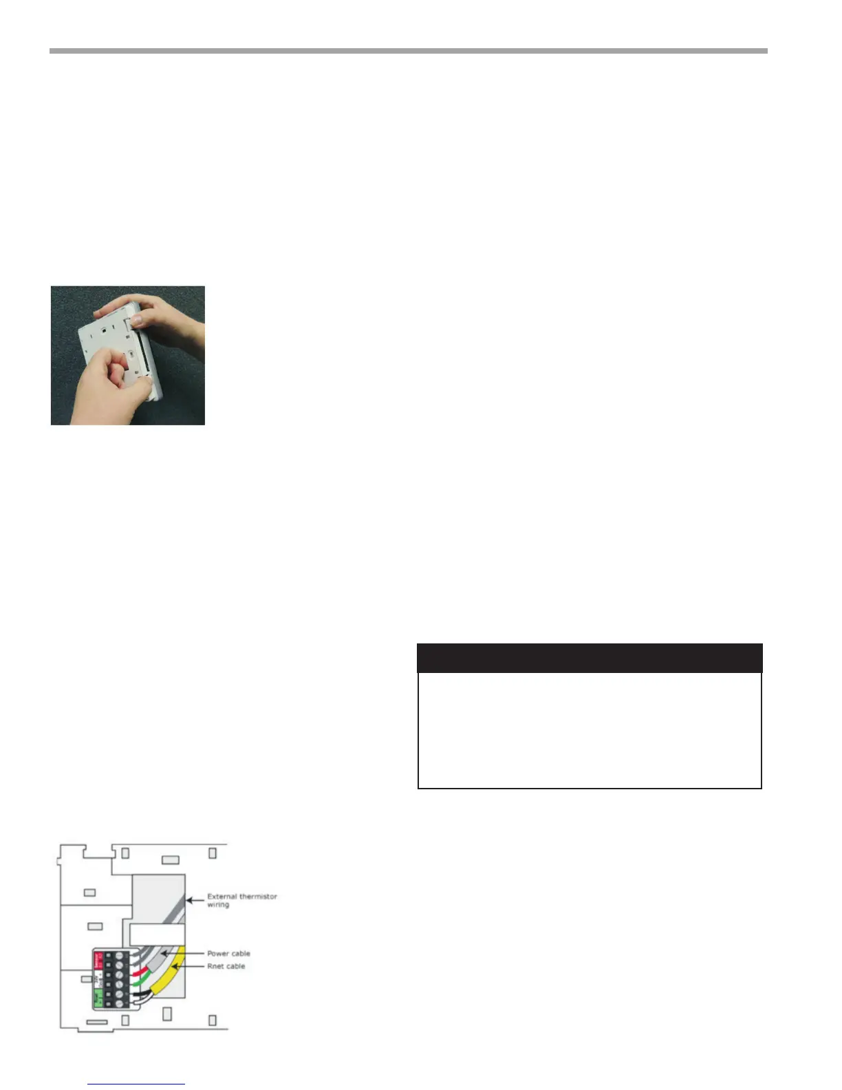
2. Pull the communication cable, power cable and
external thermistor wiring (if applicable) through the
large hole in the center of the backplate.
3. Partially cut, then bend and pull off the outer
jacket of the RNet cable(s). Do not nick the individual
wire insulation.
4. If wiring 1 cable to the Equipment Touch, cut the
shield wire off at the outer jacket, then wrap the
cable with tape at the outer jacket to cover the end
of the shield wire. If wiring 2 cables in a daisy-chain
conguration, twist together the shield wires, then
wrap the cable with tape.
5. Strip about 0.25 inch (0.6) insulation from the end
of each wire.
6. Connect wiring to the Equipment Touch as
shown below:
7. Attatch the backplate to the wall or panel.
If mounting in or on a panel:
a. Drill two 3/16 inch (4.8mm) pilot holes in
the panel.
b. Attatch a backplate using pan head 6-32 x 3/8"
to 1/2" long machine screws. Do not over tighten
screws to prevent damage to plastic housing.
Recommendation: Use Loctite 220 on screw
threads if the Equipment Touch will be subject
to vibration.
8. Attatch the Equipment Touch to the backplate:
a. Place the bottom of the equipment touch onto
the backplate by aligning the 2 slots on the
Equipment Touch with the tabs on the backplate.
b. Push the Equipment Touch onto the backplate
until the tabs at the top of the Equipment Touch
snap onto the backplate.
9. Turn off the controller's Power.
10. Connect the other end of the RNet wiring to the
controller's RNet port or to a zone sensor.
Notes- Insert the shield wire with the ground wire
into the controller's GND terminal. Use the same
polarity throughout the RNet.
11. Connect power wiring to a 24 Vac power supply.
12. Turn on the controller's power.
Allow no more than 0.6 inch (1.5mm) bare
communication wire to protrude. If bare
communiaction wire contacts the cables foil
shield, shield wire or a metal surface other than the
terminal block, the device may not communicate
correctly.
� CAUTION! �
Figure 15:
Figure 16: