THE SMART SOLUTION FOR ENERGY EFFICIENCY
MPC MultiProtoCol DDC Controls
November 19, 2018
12
BACview6 Service Tool and Addressing
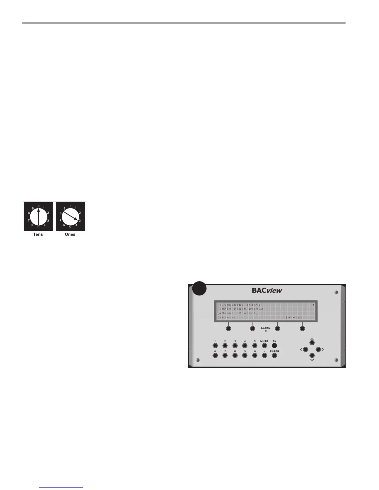
Before setting or changing the module's hardware
address, make sure the MPC Controller power is off. The
MPC only reads the address when the module is turned
on. The MPC has two rotary switches for assigning the
module’s hardware address. One switch corresponds to
the “tens” digit and the second switch corresponds to
the “ones” digit, allowing for hardware- based address-
ing of up to address 99. For example, if the module’s
address is three, set the tens switch to zero and the
ones switch to three. The station ID for each MS/TP
node must be unique on a MS/TP segment. The MPC’s
rotary address switches are used to set this unique ID.
Addressing & Power Up
Changing the device instance when using a network
of more than 99 MPC units
Note – This applies to Gen4 MPC’s only. When using
Gen3 MPC’s, to allow for more than 99 unique addresses,
a special request should be made through the Product
Management and Applications team.
The Gen 4, 5 and 6 MPC allows the device instance
to be changed using the BACview6 service tool. This
feature allows an installation with more than 99 MPC-
based units to be set and managed on-site rather than
factory preset.
In order to change the device instance, the MPC must
be powered up. Connect the BACview6 service tool to
the MPC using the local access port. When the main
screen appears, scroll down to “Manual Control” using
the down arrow and press “Enter”;
At the “Manual Control” screen, press “Enter” with
“Unit Conguration” highlighted and again with “BAC-
net” highlighted. The following screen should appear:
1
Figure 8: Setting Module Address
Note: Set address for heat pump #1 (HP-1) at 02 per
typical BMS naming conventions. All other heat pump
addresses should be assigned as HP# + 1.
After setting the address, turn power on to the MPC.
The Run, Error, and Power LEDs should turn on. The Run
LED should begin to blink and the Error LED should
turn off.
Figure 9: