THE SMART SOLUTION FOR ENERGY EFFICIENCY
MPC MultiProtoCol DDC Controls
November 19, 2018
22
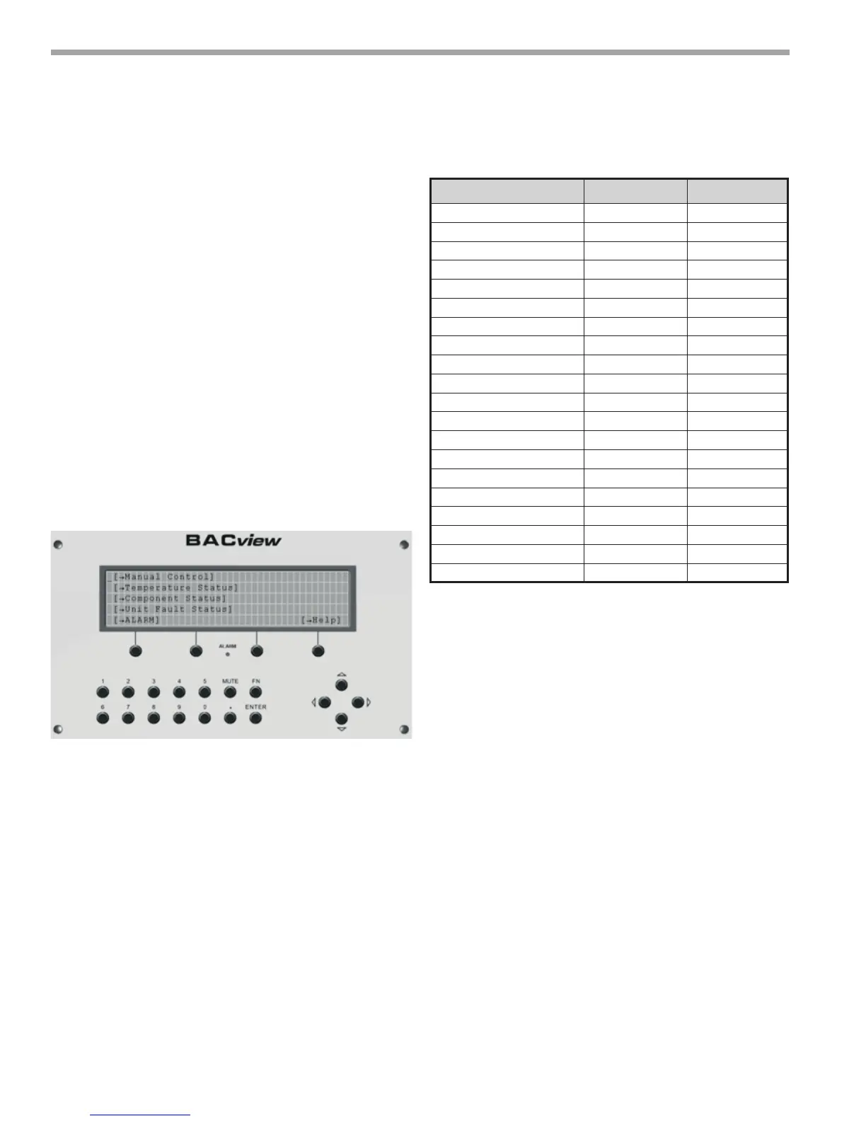
5. Navigate to “AUX Output Conguration” by
highlighting [Manual Control] and clicking <Enter>,
then highlighting [Unit Conguration], and clicking
<Enter> cursor down the list and make sure “AUX
OUTPUT” Conguration is set to 1 and Supply Fan
Conguration is set to 1.
6. Navigate to Zone Temperature Control settings by
highlighting [Manual Control] and clicking <Enter>,
then highlighting [Zone Temperature Control], and
clicking <Enter> cursor down the list and make sure
“Occupied Mode” is set to Occupied and “Metric
Mode” is OFF.
Description Point Default
Test Mode OFF
Reversing Valve Output OFF
Supply Fan Output OFF
Compressor 1 Output OFF
Compressor 2 Output OFF
Auxillary Output OFF
Supply Fan Mode AUTO
Dirty Filter Interval 1500
Emergency Shutdown OFF
Heating Mode ON
Cooling Mode ON
Dirty Filter Mode Time
Load Balance Select 2
EXT OCC/ Dirty FILT Sens OCC
Archive Enable OFF
RNET Sens1 Enable ON
RNET Sens2 Enable OFF
RNET Sens 3 Enable OFF
RNET Sens4 Enable OFF
RNET Sens5 Enable OFF
Water-to-Air Startup Check-
BACview6 Method
1. Unit is Powered up?
YES: Go to step 2
NO: Apply power to MPC.
2. Check Led status.
a. Green (TxD) LED should be blinking rapidly.
b: Green Power LED should be “ON” Solid
(not Blinking).
c: Green RUN LED should be blinking at 1-2
blinks per second.
d: RED error LED should be "OFF".
YES: Go to step 3.
3. Power down the MPC and wire up the BACview6
Service Tool and ZS Sensor(s). Once these are
installed, power MPC back up. The BACview6 should
power up and display the “Main” (Home)
4. Navigate to the “Sensor Setup and Status” screen
by highlighting [Manual Control] and clicking
<Enter>, then highlighting [Unit Control], and
clicking <Enter> cursor down the list and make sure
the following are set correctly.
Figure17: Main menu screen
MPC Sequence of Operation
Table 7: