THE SMART SOLUTION FOR ENERGY EFFICIENCY
MPC MultiProtoCol DDC Controls
November 19, 2018
68
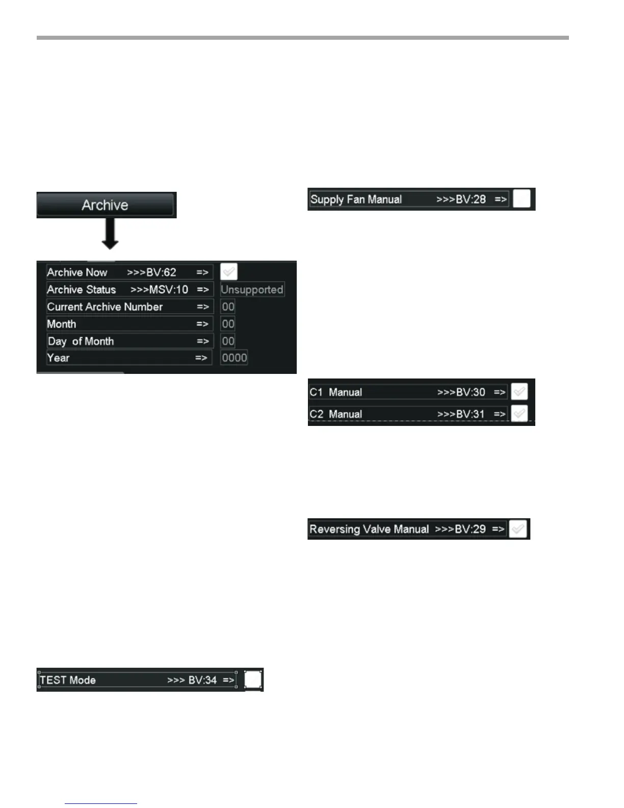
Generating a Field Archive
To archive the current MPC Download, navigate to the
ARCHIVE Screen and click the ARCHIVE NOW checkbox.
When the Archive Now Box is checked the MPC will
archive the current modied program including all control
settings and display the current archive number, Month,
Day and Year of the Archive will be displayed. See above
information on retrieval procedures.
Test Mode
Test Mode allows the Field personnel to manually
manipulate the following feature for troubleshooting
purposes:
1. Compressor 1
2. Compressor 2
3. Supply Fan
4. Reversing Valve
To enter TEST mode, the user should navigate to the
MODE Settings Screen. Once in this screen. Check the
box for TEST Mode. By navigating to the Maintenance
Screen you should see the Icon for Test Mode and should
see no ICONs for C1, C2, RV, or the FAN Icon.
The Correct Test Sequence is Shown below: Note the
Compressors will not turn on unless the Supply FAN is
ON, so it must be turned on rst.
1. To Test the Supply FAN, go to the FAN/Filter Control
Screen and check Supply FAN Manual. Check the
Maintenance Screen and ensure the FAN ICON is
present.
2. To test the Compressors, navigate to the
Compressor Setup Screen. Once here you can turn
on and turn off the compressors via the Manual
Compressor Check Boxes. As this is done the ICON’s
on the Maintenance screen will appear and disappear
according to the individual compressors being turned
on and off.
3. To test the Reversing Valve function, navigate to the
HEAT/COOL Control Screen and check the Reversing
Valve Manual checkbox. You can verify that the RV
Icon appears on the Maintenance screen when the RV
is turned on.
Figure 58:
Figure 59:
Figure 60:
Figure 61: