THE SMART SOLUTION FOR ENERGY EFFICIENCY
MPC MultiProtoCol DDC Controls
November 19, 2018
58
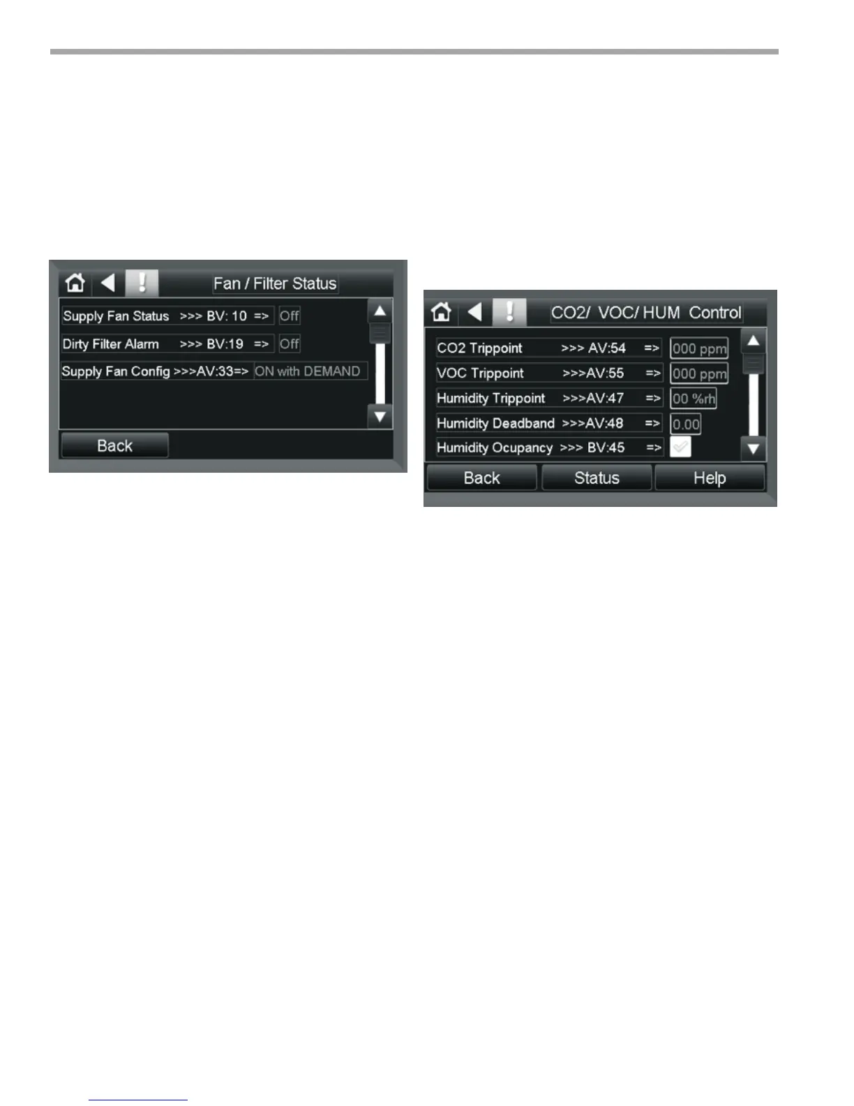
Fan/ Filter Control Status Screen
Provides access to the FAN/ Dirty Filter Alarm
Status points.
Status points associated with this screen are
described below:
1. Supply Fan Status- Reports whether the Supply Fan
is Off or On.
2. Dirty Filter Alarm- Reports whether the Dirty Filter
Alarm is Off or On.
3. Supply Fan Cong- Reports the Current
conguration of the Supply Fan. The valid states
are as follows:
a. ON with Demand
b. ON While Occupied
c. ON all the Time
CO2/ VOC/ Humidity Control Screen
Password Protected
This Screen contains all points associated with setting
the trip points and access to the status sub screen for the
CO2/ VOC/ Humidity sensors.
Control Points associated with this screen are
shown below:
1. CO2 Trip point- Sets the trip level of the CO2 sensor
in Parts Per Million (PPM).
2. VOC Trip point- Sets the trip level of the VOC
sensor in Parts Per Million (PPM).
3. Humidity Trip point- Sets the trip level of the RH
sensor in percent Humidity (%RH). There is no alarm
associated with this as exceeding the trip point is
used to turn on the AUX output only when in Relative
Humidity mode.
4. Humidity Dead band- Subtracts the Dead Band
value from the Setpoint value keeping the AUX from
responding until it has exceeded the setpoint by the
Dead Band value:
Example: If the setpoint is 30 % and the Dead Band
is 2%, the AUX will not respond until it reaches
32% R.H. So AUX will not trip until it reaches the
SETPOINT + Dead Band.
5. Humidity Occupancy- This point controls the
actuation of the AUX output in Relative Humidity
mode. When Off the Aux output goes on when the
Trip Point is exceeded and the MPC is in Occupancy
Mode. When It is ON the AUX output will respond
anytime the setpoint is exceeded regardless of
Occupancy status.
Equipment Touch Screen Descriptions
Figure 38:
Figure 39: