THE SMART SOLUTION FOR ENERGY EFFICIENCY
MPC MultiProtoCol DDC Controls
November 19, 2018
46
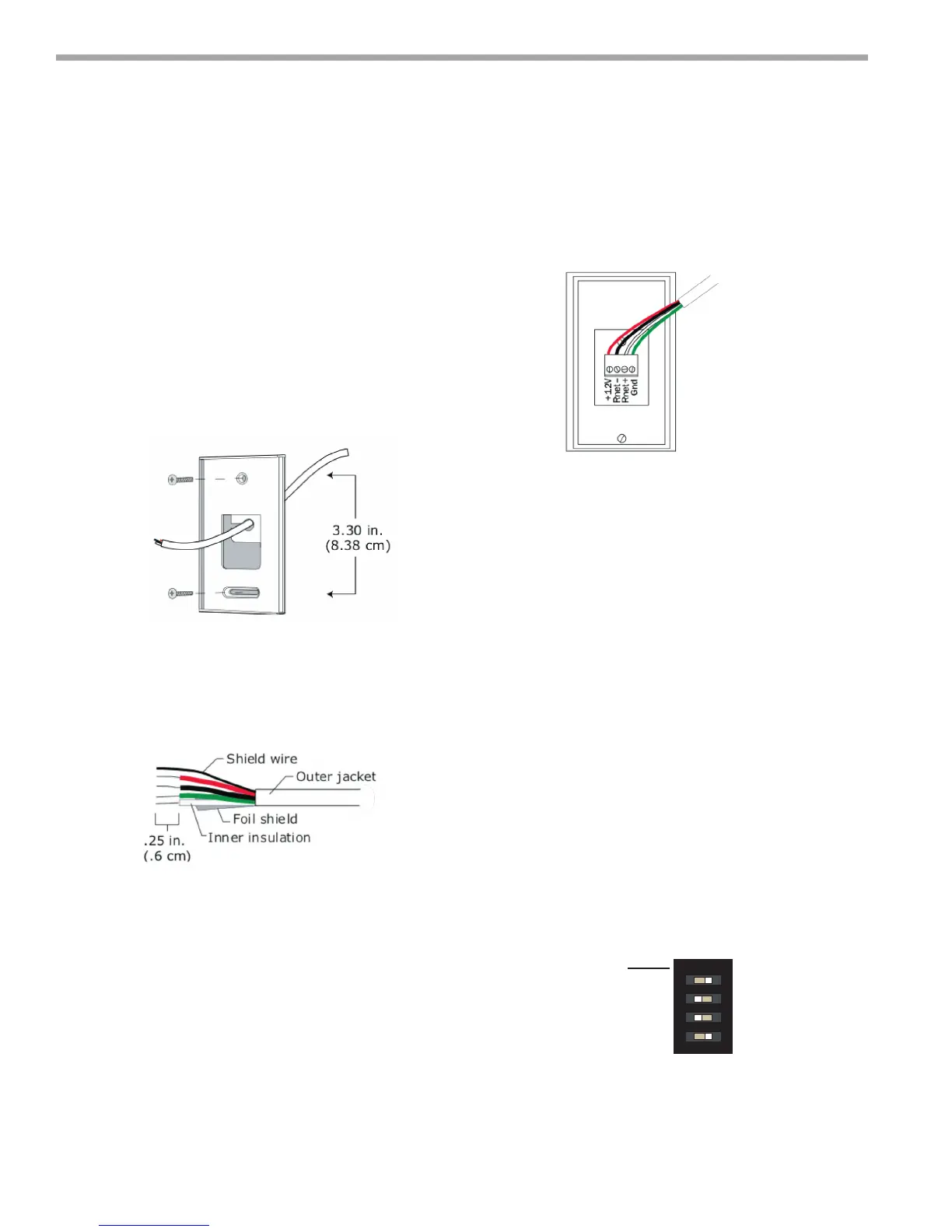
To wire and mount a ASW13-15 Sensor
PREREQUISITE: The RNet cable is wired to the controller.
The shield wire and the ground wire should
be inserted into the controller's GND terminal.
1. Turn off the controller's power.
2. Pull the backplate off the RNet Sensor. You may need
to turn the setscrew in the bottom of the sensor
clockwise until you can remove the backplate.
3. Pull the RNet communication cable through the large
rectangle in the backplate.
4. Use 2 screws to mount the backplate to the wall or
outlet box.
5. Partially cut, then bend and pull off the outer jacket
of the RNet cable(s). Do not nick the inner insulation.
6. Strip about .25 inch (.6 cm) of the inner insulation
from each wire.
7. If wiring 1 cable to the RNet Sensor, cut the shield
wire off at the outer jacket, then wrap the cable with
tape at the outer jacket to cover the end of the shield
wire. If wiring 2 cables in a daisy-chain conguration,
twist together the shield wires, then wrap the shield
wires with tape.
To this terminal...
+12V
Rnet-
Rnet+
Gnd
CAUTION: Allow no more than .06 inch (1.5 mm)
bare communication wire to protrude. If bare
communication wire contacts the cable's foil shield,
shield wire, or a metal surface other than the terminal
block, the sensor may not communicate correctly.
ASW 13,14,15 Wall Sensors (RNET Sensors)
8. Insert the other 4 wires into the RNet Sensor's screw
terminal connector. If wiring 2 cables, insert like-
colored wires into each terminal.
Climatemaster recommends that you use the
following RNet wiring scheme:
Connect this wire...
Red
Black
White
Green
10. Attach the sensor's cover and circuit board to the
mounted backplate, inserting the top rst.
11. Tur n the setscrew one full turn counterclockwise so
that the cover cannot be removed.
12. Tur n on the controller's power.
To address a ASW13-15 Sensor
Each ASW13-15 Sensor on an RNet must have a unique
address, but addresses do not have to be sequential.
Use the DIP switches on the back of the RNet Sensor to
set an address from 0 to 14 (0 is factory default) Each DIP
switch has the value shown in the gure below. Turn on as
many DIP switches as you need so that their total value
equals the address.
EXAMPLE: DIP switches 1 and 4 above are on. Their values
(1 + 8) total 9, so the sensor's address is 9.
ASW LED indicator on the wall sensor turns ‘on’ during
Occupied Mode and turns ‘off’ during "Unoccupied" Mode.
wit ch
value
1
2
4
8
1 2 3 4
Figure 18:
Figure 19:
Figure 20:
Figure 21: