THE SMART SOLUTION FOR ENERGY EFFICIENCY
MPC MultiProtoCol DDC Controls
November 19, 2018
62
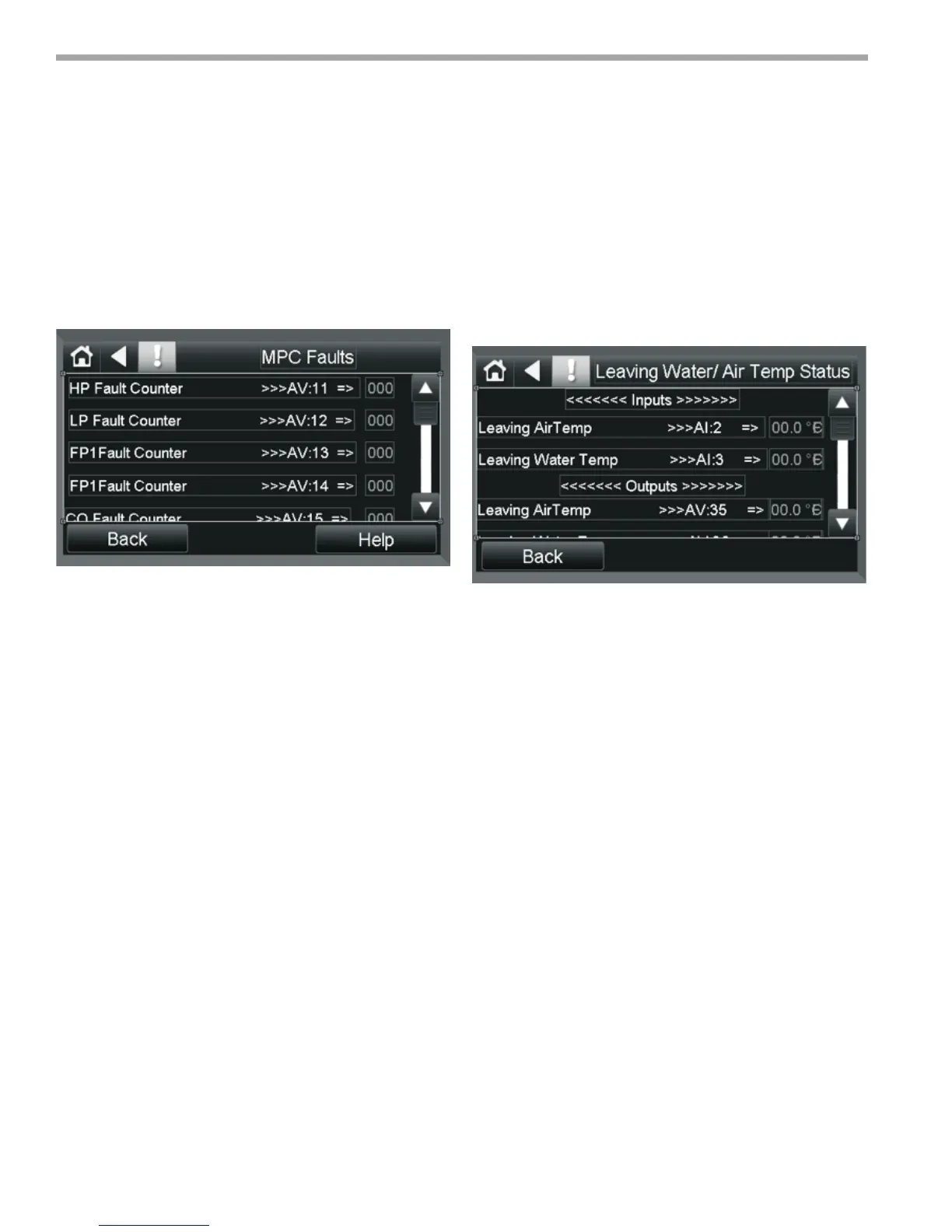
MPC Faults
This screen reports the fault count for various fault types
and includes the reset function to clear those same
faults. For more information on these faults, please refer
to the DXM2 Software specication.
1. HP Fault Counter- High Pressure fault counter.
2. LP Fault Counter- Low Pressure fault counter.
3. FP1 Fault Counter- Freeze Protect 1 Fault
(open or shorted).
4. FP2 Fault Counter- Freeze Protect 2 Fault
(open or shorted).
5. CO Fault Counter- Condensate Overow
fault alarm.
6. Over/Under Fault Counter- Over/Under Voltage
Fault detection alarm.
7. UPS Fault Counter- Unit Performance Sentinel Fault.
8. Swapped FP1/FP2 Fault- Indicated FP1 and FP2 are
swapped or reversed.
9. Airow Fault Counter- Airow Fault
10. Pump Fault Counter- Pump Fault
11. Fault- Aggregate Fault number
12. Pulse Signal Value- Previous Pulse Alarms counts
from external Controller.
13. UPS Signal Enable- Reports the status of the Unit
Performance Sentinel.
14. Valid Sensor- Valid Sensor Detected
15. Fault Count Reset- Resets all Fault Counters
when ON
LAT/ LWT Status
This screen reports the Leaving Air Temperature and
the Leaving Water Temperature status. These points do
not affect control of the MPC unit but instead are for
reporting purposes for the BMS and are available via
analog outputs 1 and 2.
1. Leaving Air Temp- Reports the Leaving Air temp
when an appropriate sensor is connected to AI:2.
2. Leaving Water Temp- Reports the Leaving Water
temp when an appropriate sensor is connected
to AI:3
3. Leaving Air Temp- Network output representing
Leaving Air Temp. It will be in F° or C° depending on
the status of the “Metric” Control point (BV:39).
4. Leaving Water Temp- Network output representing
Leaving Water Temp. It will be in F° or C° depending
on the status of the “Metric” Control point (BV:39).
5. RS: LAT- Leaving Air Temperature analog output
6. LRS: LWT- Leaving Water Temperature analog
output.
Equipment Touch Screen Descriptions
Figure 46:
Figure 47: