THE SMART SOLUTION FOR ENERGY EFFICIENCY
MPC MultiProtoCol DDC Controls
November 19, 2018
51
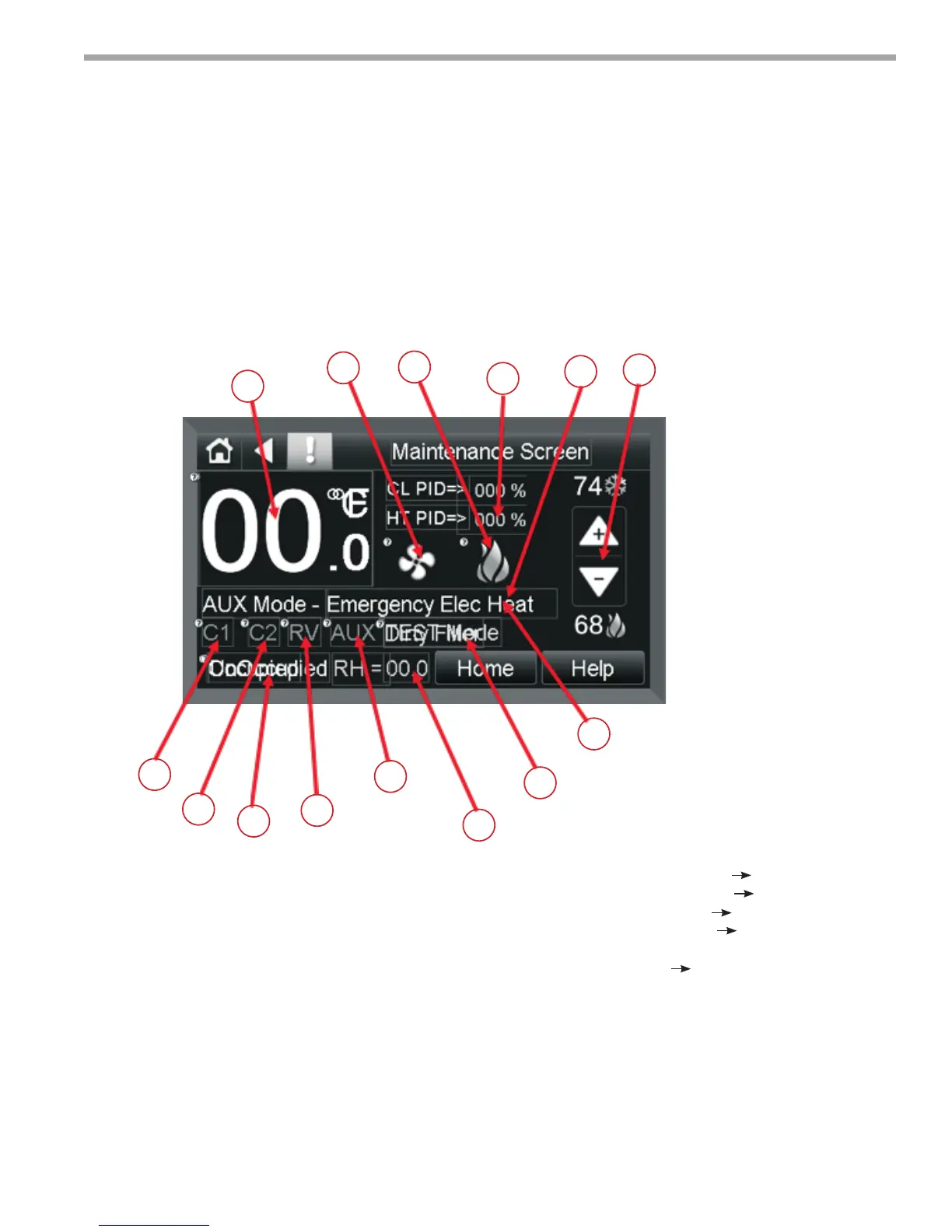
Figure 26:
Equipment Touch Manual - Screen Descriptions
Maintenance Screen
The Maintenance Screen is used to monitor normal
operation of the MPC unit and contain various status
points. Using the Home Icon or Home button will return
the user to the Home Screen. For information on the
Maintenance screen the Help Button will provide help on
the meaning and use of the Icons used in the Screen.
1. Compressor Stage 1 “ON” when C1 icon is visible.
2. Compressor Stage 2 “ON” when C2 icon is visible.
3. Reversing Valve 2 “ON” when RV icon is visible.
4. Auxiliary Output 2 “ON” when AUX icon is visible.
5. Occupancy Status <Unoccupied or Occupied>
6. Fan Output “ON” when Fan icon is visible.
7. Heating PID %
8. Cooling PID %
9. Zone Temperature
10. AUX Mode setting
11. Heating/cooling setpoints
12. Heat/cool Icons displayed when greater than
50% demand.
13. Relative Humidity Display
14. Test Mode/Dirty Air Filter Mode
9
1
2
5
3
4
13
14
10
6
7
8
12
11