THE SMART SOLUTION FOR ENERGY EFFICIENCY
MPC MultiProtoCol DDC Controls
November 19, 2018
19
Water -to-Water Start Up Check
1. Unit powered up and running.
2. LED check: Rx, Tx, Power, Run and no solid
red error led.
3. Program initializing schedule status for Occupied
Mode (default) or Unoccupied Mode to determine
set point range. Occupied set points will be
defaulted to 60 cooling and 105 heating. If a
schedule is implemented, the unoccupied set points
will default to 80 cooling and 85 heating.
4. The Program will determine if the unit is either a
Master or Slave.
5. The Program will control the water temperature
based on the Entering Water Temperature (EWT)
load sensor. This can be changed to control based
off of the LWT via BAS or BACview6 service tool.
6. The Program will check for which water temperature
set point to use based on Heating Mode or Cooling
Mode determined by the state of the RV.
7. In a water to water application, the mode has to be
manually changed via Bacnet or with BACVIEW6
service tool. If it is in heating, it will permanently stay
in heating mode until it is changed to specically
cooling mode.
8. Like water to air, Y1 will come on a 50% and Y2 at
75% and not off until the EWT/LWT conditions have
been satised.
9. 5-minute delay is built in between compressor cycles.
10. While the unit is on, the program will continue to
monitor the CXM/DXM/DXM2 board for faults. If
an event of a fault occurs and the unit is in lockout
mode, then the relay will close (IN1/AL1/AL2/GND)
and the fault code is transmitted via EH2 output to
the EHZ input on the MPC. This is available through
BAS network points. A history counter will also keep
track of past and present faults which can also be
seen via BAS or BACview6.
11. The MPC can also function in metric mode
(Celsius mode).
MPC Sequence of Operation
Water-to-Air Startup Check-
Equipment Touch Method
1. Unit is Powered up?
YES: Go to step 2
NO: Apply power to MPC.
2. Check Led status.
a. Green (TxD) LED should be blinking rapidly.
b: Green power LED should be on solid .
c: Green RUN LED should be blinking at 1-2
blinks per second.
d: RED error LED should be off.
YES: Go to step 3.
Power down MPC and wire up the Equipment Touch
Service Tool and RNet Sensor(s). Once these are
installed, power MPC back up.The Equipment Touch
should power up and display the “Main” (Home)
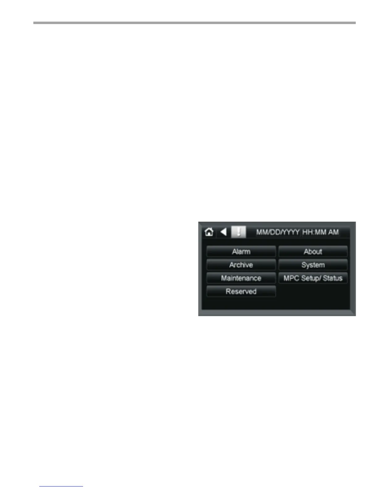
3. Navigate to the “Sensor Setup and Status” screen
by pressing <MPC Setup/Status> then <Sensor
Setup/Status> buttons. Press the <ZS Sens Active>
button. This should display the correct address and
number of ZS Sensors that are attached to the MPC.
Press the <Back> and go to the “ZS Sensor Setup”
screen where you will need to enable the alarms for
each sensor installed and detected in the previous
step.
4. From the EQT menu press <Temp Setup and
Status> then press <Temp Units>. “Current Mode”
should be set to <Fahrenheit>. If this is ok, you are
nished here and can move on to Step 5. Otherwise
uncheck the “Metric Mode” (BV:39) point to set the
MPC to Fahrenheit mode. Make sure the “Current
Mode” changes to “FAHRENHEIT” before pressing
<BACK> and exiting this screen.
Figure 16: Menus screen