THE SMART SOLUTION FOR ENERGY EFFICIENCY
MPC MultiProtoCol DDC Controls
November 19, 2018
20
From the <Temp Setup and Status> screen press
<Temp Setpoints>.
• The default settings for the Fahrenheit and Celsius
operation modes are listed here in this screen. If
your setpoints differ from the default values listed
here, please enter them in the appropriate box.
• Press the <Manual SP> button to go to the
“MANUAL SP” Screen in which you can edit
the Manual Setpoint Adjust Range. It is defaulted
to +/- 5° Fahrenheit or 2.8 ° Celsius. This will
allow you to have a 10 F° / 4.6 C° adjustment
range of the setpoint from the sensor. If you wish
a looser or tighter range, please enter it now.
Note: if it is set to zero, no adjustment can
be made from the Wall Sensor.
5. The MPC will default to RNet Sensors. If you have
LSTAT Sensor types you will need to set jumper W3
to LSTAT.
6. From the “MPC Setup/Status” screen press
<Compressor Setup>. Please check the compressor
setting to ensure all are set to the default factory
settings. Load Balance Select controls the stage
assignment of compressors. The default setting
assigns compressor 1 as primary and compressor 2
as secondary. Note: For single compressor systems
C1 should always be primary.
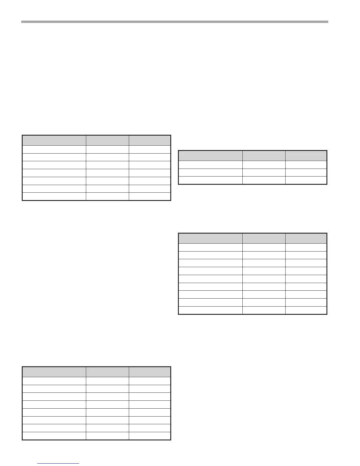
Description Fahrenheit° Celsius°
Master Zone Temp 73.0 22.7
Unoccupied Dead Band 17 9.44
Occupied Dead Band 2 1.11
Unoccupied Heat Setpoint 82 27.7
Occupied Cool Setpoint 74 23.3
Slave Heat Setpoint 72 22.2
Slave Cool Setpoint 74 23.3
Description Point Default
Load Balance Select AV:59 2
Compressor Shut Down BV:53 Unchecked
C1 Manual BV:30 Unchecked
C2 Manual BV:31 Unchecked
C1 Runtime Reset BV:2 Unchecked
C2 Runtime Reset BV:5 Unchecked
C1 Cycle Reset BV:21 Unchecked
C2 Cycle Reset BV:22 Unchecked
MPC Sequence of Operation
7. From the “MPC Setup/Status” screen press <Heat/
Cool Control>. Ensure that the following points
are set to the default values. The default values
enable both the heating and cooling modes and
ensures the reversing value is not in manual mode.
If you need “Heat Only” or “Cool Only” modes,
uncheck the appropriate enable for the mode you
wish to disable. 99% of all applications will have both
enabled.
8. From the <MPC Setup/Status> screen press <Fan/
Filter Control>.Check the following point for the
correct default value. The Supply FAN is congured
to cycle anytime the compressor is “ON”.
9. From the “MPC Setup/Status” screen press <Heat/
Cool Control>. Check Occupancy BV:12 and make
sure it is set to “Occupancy”.
From the “MPC Setup/Status” screen press
<AUX Outputs>. Check the “AUX CFG” setting
for the default value of 1. This is Emergency Electric
Heat. If other functions are needed please consult
the Control Points Matrix for other functional
settings associated with this point.
Description Point Default
Heat Mode Enabled BV:61 Checked
Cool Mode Enabled BV:54 Checked
Reversing Valve Manual BV:30 Unchecked
Description Point Default
Emergency Shutdown BV:8 Unchecked
Supply Fan Manual BV:28 Unchecked
Supply Fan Congure AV:33 1
Dirty Filter Reset BV:7 Unchecked
Dirty Filter Interval AV:30 1500
Dirty Filter Mode BV:60 Time
Dirty Filter Sens BV:59 Unchecked
Fan Speed Enable BV:51 Unchecked
Fan Speed Trigger Type AV:56 75%
Table 3:
Table 4:
Table 5:
Table 6: