Site considerations
98-175666-A Chapter 2: Installation 2-9
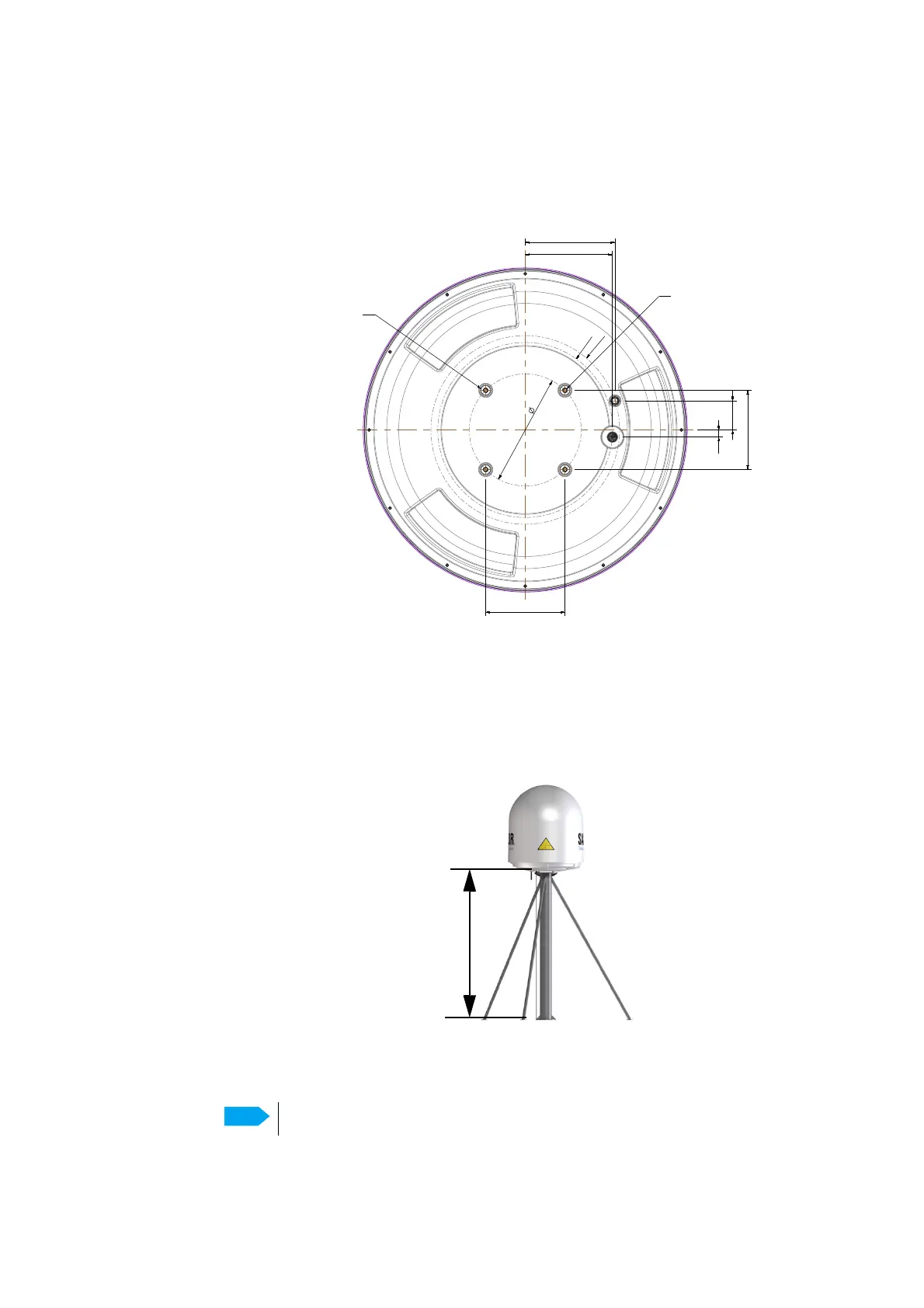
5. Use the dimensions in the following figure to prepare the mast flange for mounting of
the ADU.
The following figure shows the bottom view of an antenna.
Mast length and diameter
The mast wall thickness is in the following design examples set to 5 mm and the brace wall
thickness to 4 mm. A larger wall thickness yields more stiffness (valid design) whereas a
thinner wall thickness yields a more weak structure (not valid design).
Figure 2-11: ADU, bottom view (60 cm)
282.8
R221
R238
18
73.5
200
200
220
226.4
THREAD for GROUNDING
M10 (depth: 22mm)
Figure 2-12: Free mast length and bracing for a tall mast
Make sure that there is free space below the drain tube.
 Loading...