Integration of a 3rd party IP device (100 cm)
98-175666-A Chapter 2: Installation 2-30
2.8 Integration of a 3rd party IP device (100 cm)
This section describes how to integrate a 3rd party device inside the antenna radome. The
antenna has the following interfaces for the integration:
• Power connector
• Communication
• Mechanical interface
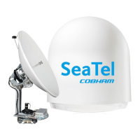
2.8.1 Power connector
The power output options are 12 VDC / 2A and 5 VDC / 2A. The physical interface is a 4-pin
nano-fit female connector on the XTR Antenna Control Module (ACM).
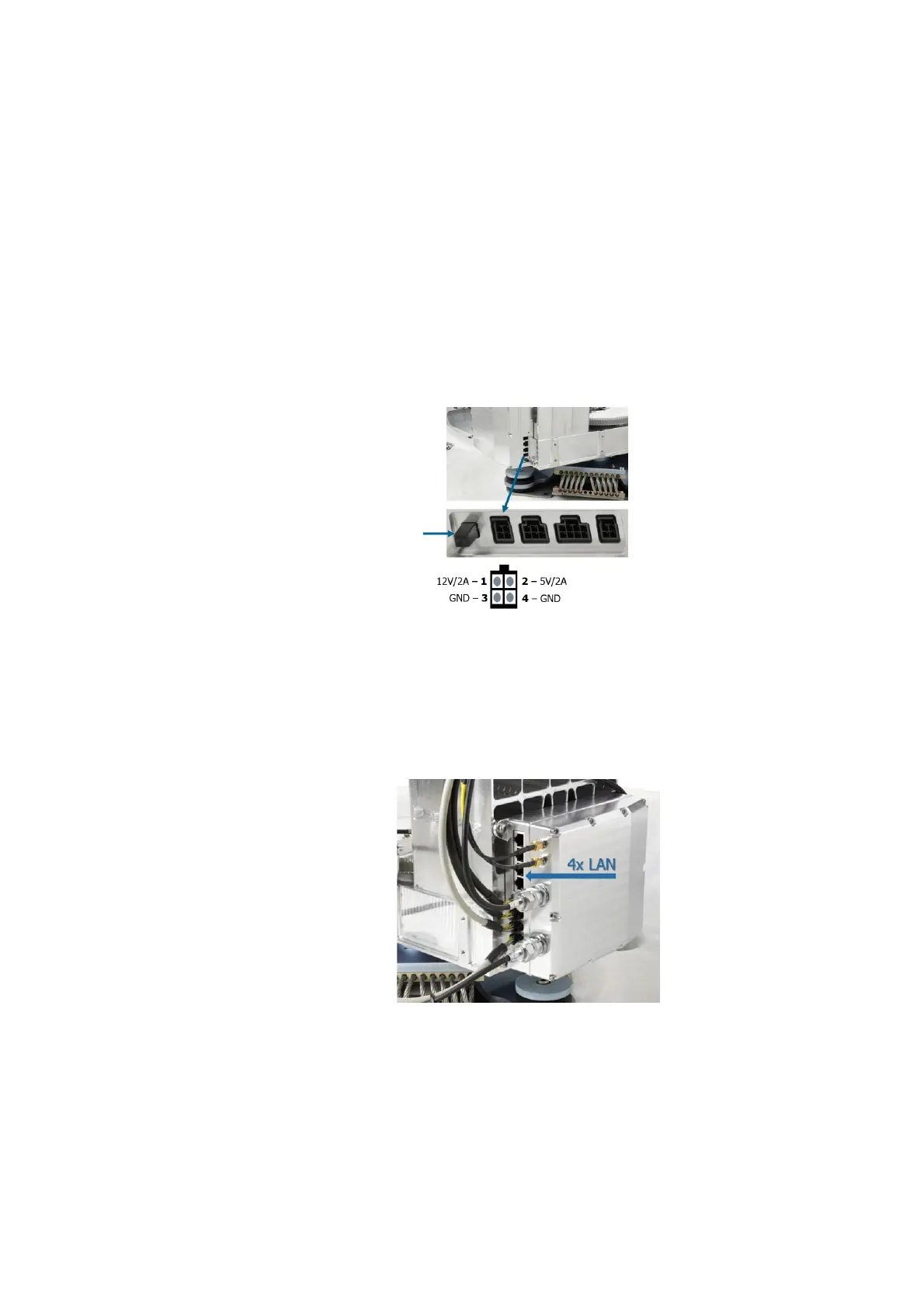
2.8.2 Communication
The ACM has four Ethernet LAN ports. LAN port 1 and 2 can be tunneled to the LAN ports
of the BDU. The BDU LAN port and ACM LAN port are a transparent data channel that
connects two devices.The ACM LAN ports are set up in the web interface
Figure 2-34: ADU power on off (left) and ACM 4-pin nano-fit connector
Figure 2-35: ACM LAN ports
 Loading...