Connector panel of the BDU
98-175666-A Chapter 3: Interfaces 3-4
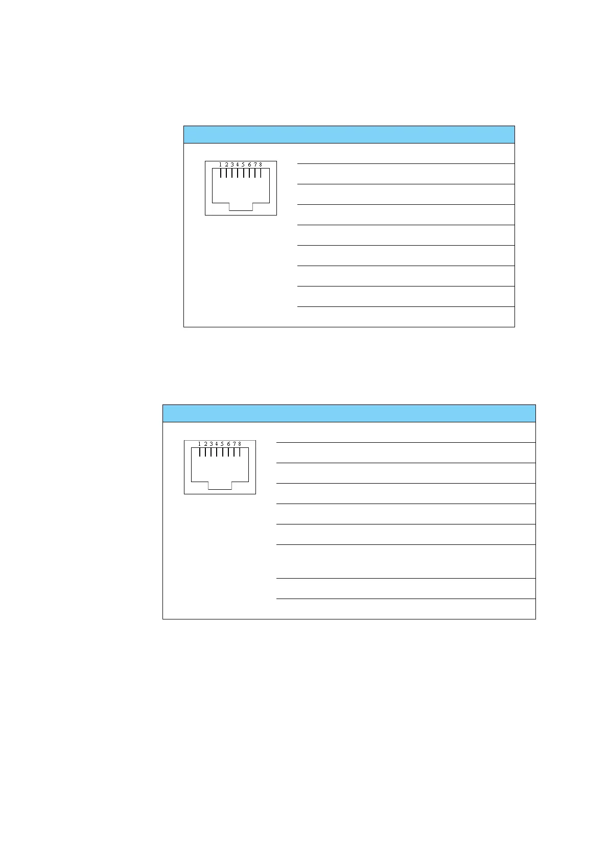
3.1.6 RS-232 RJ-45 connector
Use the following connector to connect the BDU to the VSAT modem.
3.1.7 RS-422 RJ-45 connector
Use the following connector to connect the BDU to the VSAT modem
Outline Pin Signal Pin function
1RSSI 2 Analog(0-14VDC)
2 DTR/Rx Lock Modem Rx lock
3RXD Receive data
4GND Ground
5GND Ground
6TXD Transmit data
7DSR/TX MuteTx mute
8RSSI 1 Analog(0-14VDC)
Shield PCB ground PCBground
Table 3-6: RJ-45 RS-232 connector, male, outline and pin assignment
Outline Pin Signal Pin function
1 Line A RXD (+) Receive data (non-inverting)
2 Line A RXD (-) Receive data (inverting)
3 Line B TXD (+) Transmit data (non-inverting)
4GND Ground
5GND Ground
6 Line B TXD (-) Transmit data (inverting)
7 BUC Key line
(+)
Key line (non-inverting)
8 BUC Key line (-) Key line (inverting)
Shield PCB ground PCB ground
Table 3-7: RS-422 connector, male, outline and pin assignment
 Loading...