Interfaces of the modem
98-175666-A Chapter 3: Interfaces 3-6
3.2.3 RS-232 and RS-422 connectors
The modem has two RS-232 and one RS-422 connector for control information to and
from the ACU. See section To connect the ADU, ACU and modem on page 3-25 for details
how to connect the BDU to the modem.
Outline
(on the BDU)
Pin
number
Pin function
1 Inner conductor: 50 MHz clock, Rx/Tx
2 Outer conductor: GND (Shield)
Table 3-9: F connector, Rx and Tx, outline and pin assignment
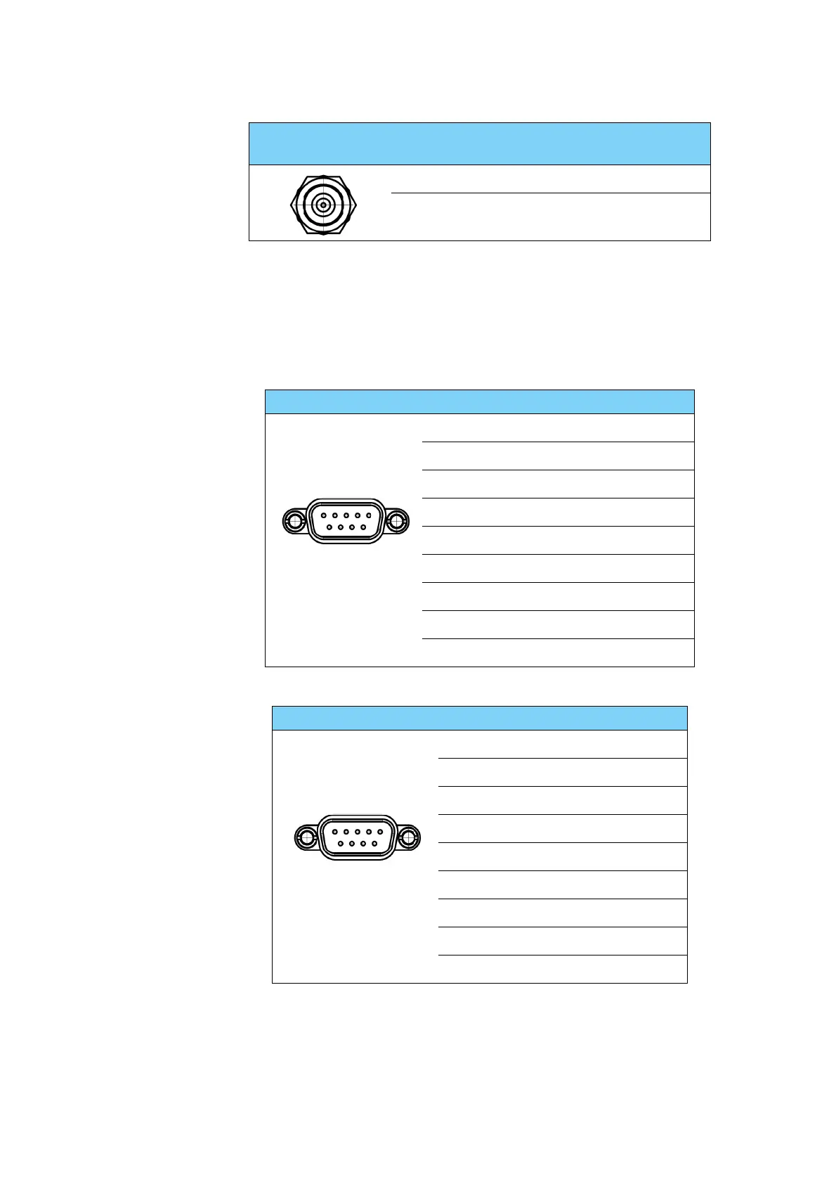
Outline (on the modem) Pin Pin function
1 Not connected
2BUC TXD
3BUC RXD
4 Not connected
5GND
6 Power good
7GMU reset
8 Temperature out of range
9 Core module RSSI
Table 3-10: RS-232 connector, male, outline and pin assignment, modem
Outline (on the modem) Pin Pin function
1GND
2 Key-line P
3 Reset P
4GND
5GND
6 Not connected
7 Key-line N
8 Reset N
9 Not connected
Table 3-11: RS-422 connector, male, outline and pin assignment, modem
 Loading...