InteliLite4 AMF20 Global Guide
592
You have proper connection with the unit
COM port selection is correct
Module has power supply, (no CAN bus connection, status LED lights continuously)
10. After successful programming disconnect AT-Link conv , remove TEST jumper and disconnect power
supply
11. Connect power supply again (status LED should blink)
12. Module FW is upgraded
LED indication
LEDstatus Description
Dark Fw in module does not work correctly.
Flashing Module does not communicate with controller (in case non-zero CAN address).
Lights
Power supply is in the range and the communication between Inteli AIN8 and controller
works properly.
Or power supply is in range and zero CAN address is set. (in case zero CAN address
module doesn't communicate with the controller).
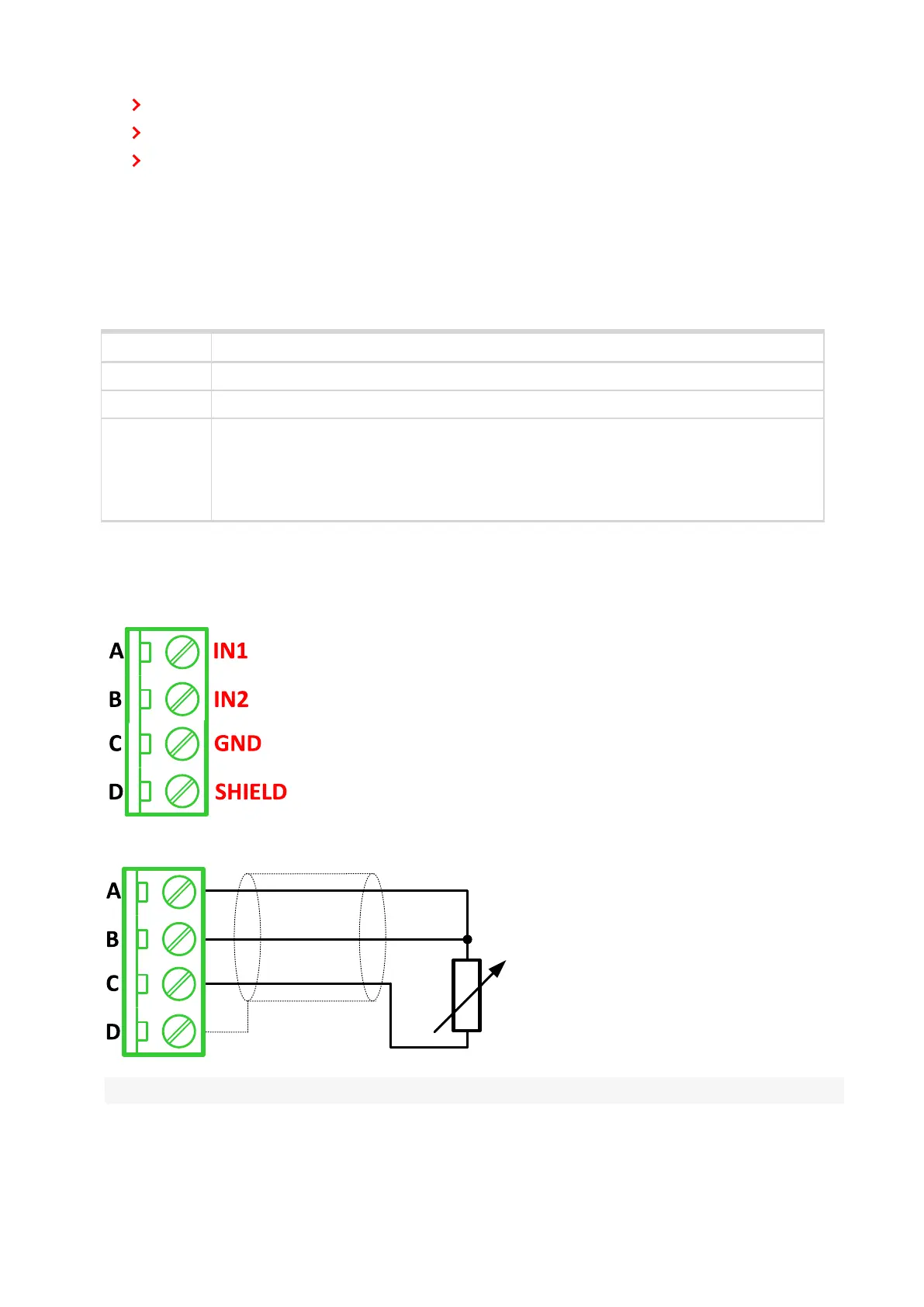
Wiring
The following diagrams show the correct connection of sensors.
Terminator
Resistance sensor - 3 wires
Note: Ranges: Pt100, Pt1000, Ni100, Ni1000, 0-2400 Ω, 0-10 kΩ