InteliLite4 AMF20 Global Guide
618
Press Lamp test sixteen times
Set the address up by pressing Horn reset.
The number of red luminous LEDs means the CAN1 addresses (two for addresses 1+2, four for
addresses 3+4, six for addresses 5+6 and eight for addresses 7+8)
Press Lamp test
LED indication
Each LED color is adjusted independently of controller output settings. If controller output 1 is set as
"Common Shutdown" it does not mean red LED1 color for iGL-RA15. The LEDs color can be adjusted by
following steps:
Switch to programming mode (Hold the Horn reset and Lamp test when unit is powering on). Status led is
yellow
Press Horn reset to change the LED1 color (green, yellow, red)
Press Lamp test to switch to the next LED color adjusting
Continue to adjust all LEDs color
After LED15 color adjusting press Lamp test three times
Note: If there is no operator action during address setting, color adjusting or timeout setting, the unit returns
to normal operation without changes saving.
Status LED
The signals LEDs are handled like binary outputs. This means everything that can be configured to binary
outputs can be also configured to the LEDs of IGL-RA15.
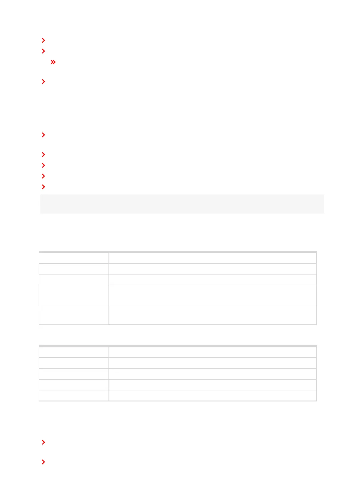
LEDstatus Description
Lights Configured logical output is active on the controller
Dark green LED Configured logical output is not active on the controller
Dark yellow or red LED
Configured logical output is not active on the controller and horn reset was
pressed.
Yellow or red LED blinks
Configured logical output is not active on the controller and horn reset was still
not pressed.
Power LED
LEDstatus Description
Blinking green The unit is OK and the communication to the master controller is OK.
Blinking red The unit is OK, but the communication to the master controller is not running.
Blinking yellow EEPROM check not passed OK after power on
Yellow Horn timeout or controller address adjustment
Horn setting
The horn output is activated if any of red or yellow LED is on. Output is on until pressing Horn reset or horn
timeout counts down. The timeout can be set via the following steps:
Switch to programming mode (Hold the Horn reset and Lamp test when unit is powering on). Status led is
yellow
Press Lamp test fifteen times